Vapor drying method, apparatus therefor and storage medium

A technology of drying method and drying device, which is applied in the direction of separation method, chemical instrument and method, sustainable manufacturing/processing, etc., can solve problems such as inert gas waste, flow limitation, and longer second drying treatment time, and achieve effective Utilize and achieve the effect of drying time

Inactive Publication Date: 2007-02-14
TOKYO ELECTRON LTD
View PDF1 Cites 1 Cited by
  • Summary
  • Abstract
  • Description
  • Claims
  • Application Information

AI Technical Summary

Problems solved by technology

[0006] In this way, the N that can be supplied to the mixing mechanism 2 The gas flow is limited because it is set within the range most suitable for IPA mixing
Therefore, if the N 2 If the gas is used for the second drying, the supply amount is small, so the second drying treatment time becomes longer, and there is a problem that the drying performance is affected by water marks, etc.
In addition, since a small amount of inert gas is supplied for a long time, there is a possibility of waste of inert gas

Method used


Image

  • Vapor drying method, apparatus therefor and storage medium
  • Vapor drying method, apparatus therefor and storage medium
  • Vapor drying method, apparatus therefor and storage medium

Examples


no. 1 Embodiment approach

[0052] Hereinafter, specific embodiments of the present invention will be described in detail based on the drawings. Here, a case where the steam drying apparatus of the present invention is applied to a semiconductor wafer rinsing and drying processing system will be described.

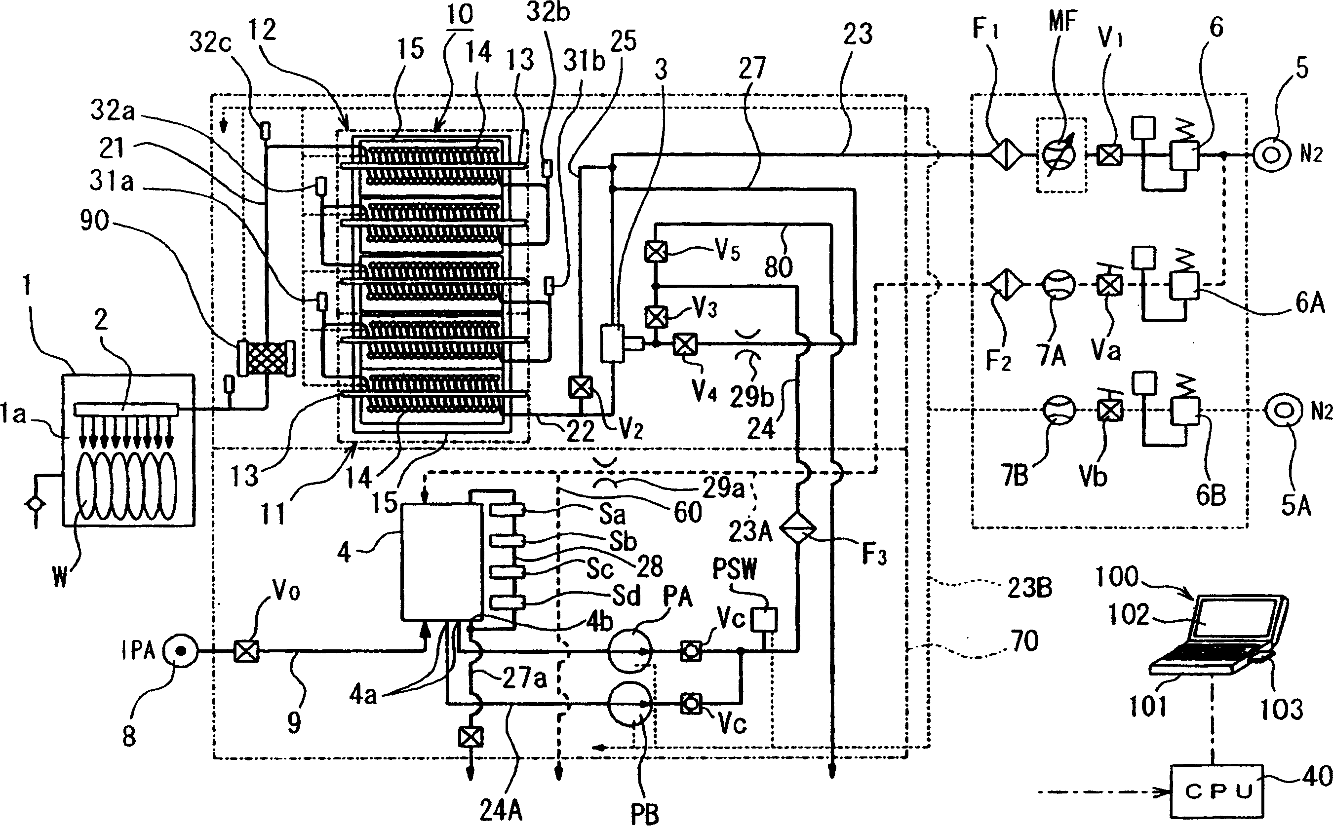
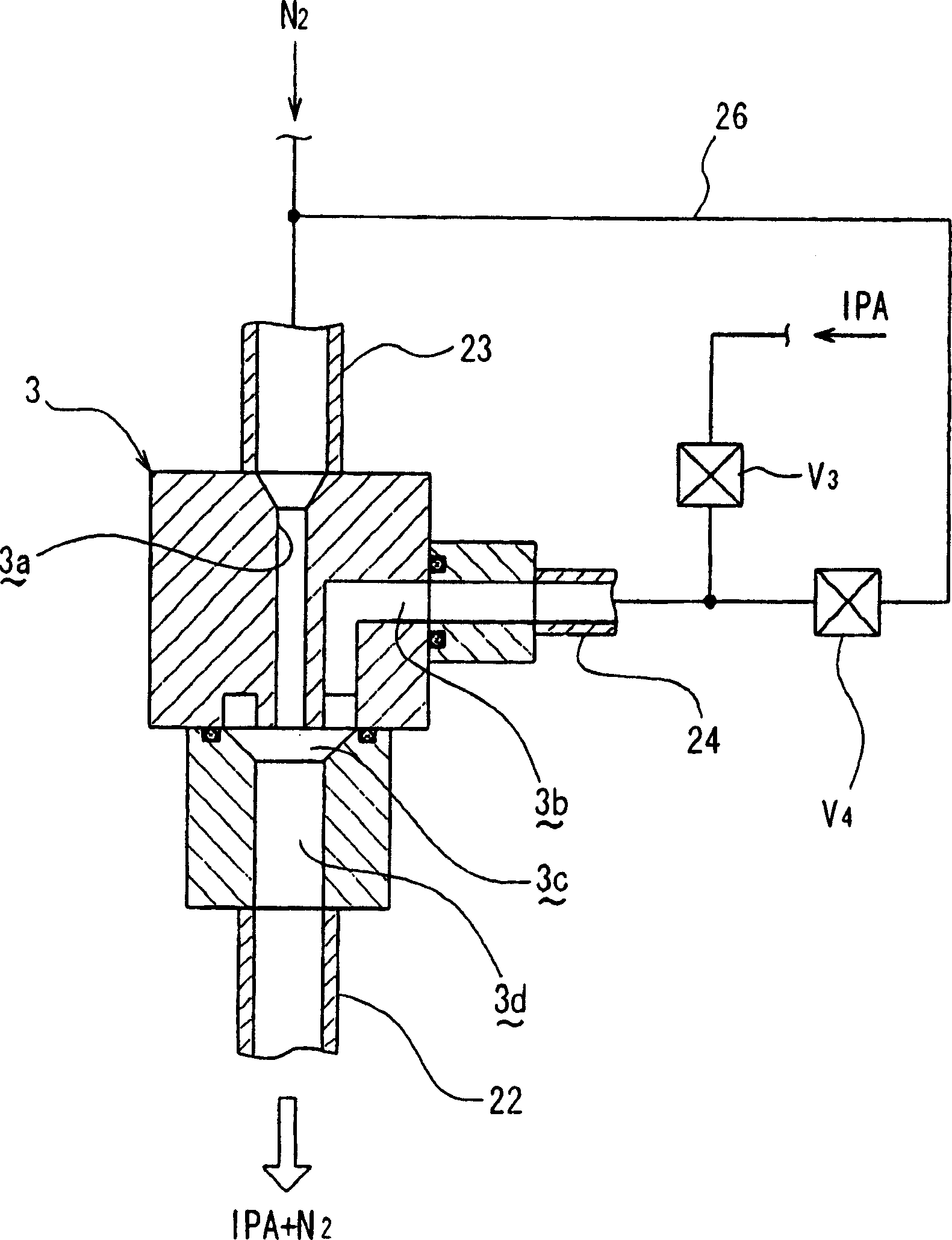
[0053] figure 1 It is a schematic configuration diagram showing the whole of the above-mentioned washing and drying treatment system, figure 2 It is a schematic sectional view showing the mixed fluid generating mechanism of the present invention.

[0054] The rinsing and drying processing system described above is provided with: a processing container 1 having a processing chamber 1a for accommodating a semiconductor wafer W (hereinafter referred to as a wafer W) as an object to be processed; (spray) drying steam or an inert gas such as nitrogen (N 2 ) gas supply mechanism; steam generator 10 is to generate IPA (isopropanol) and N as steam solvent 2 The steam generating mechanism of the steam of...

no. 2 Embodiment approach

[0093] Hereinafter, preferred embodiments of the present invention will be described in detail based on the drawings. Here, a case where the steam drying apparatus of the present invention is applied to a semiconductor wafer rinsing and drying processing system will be described.

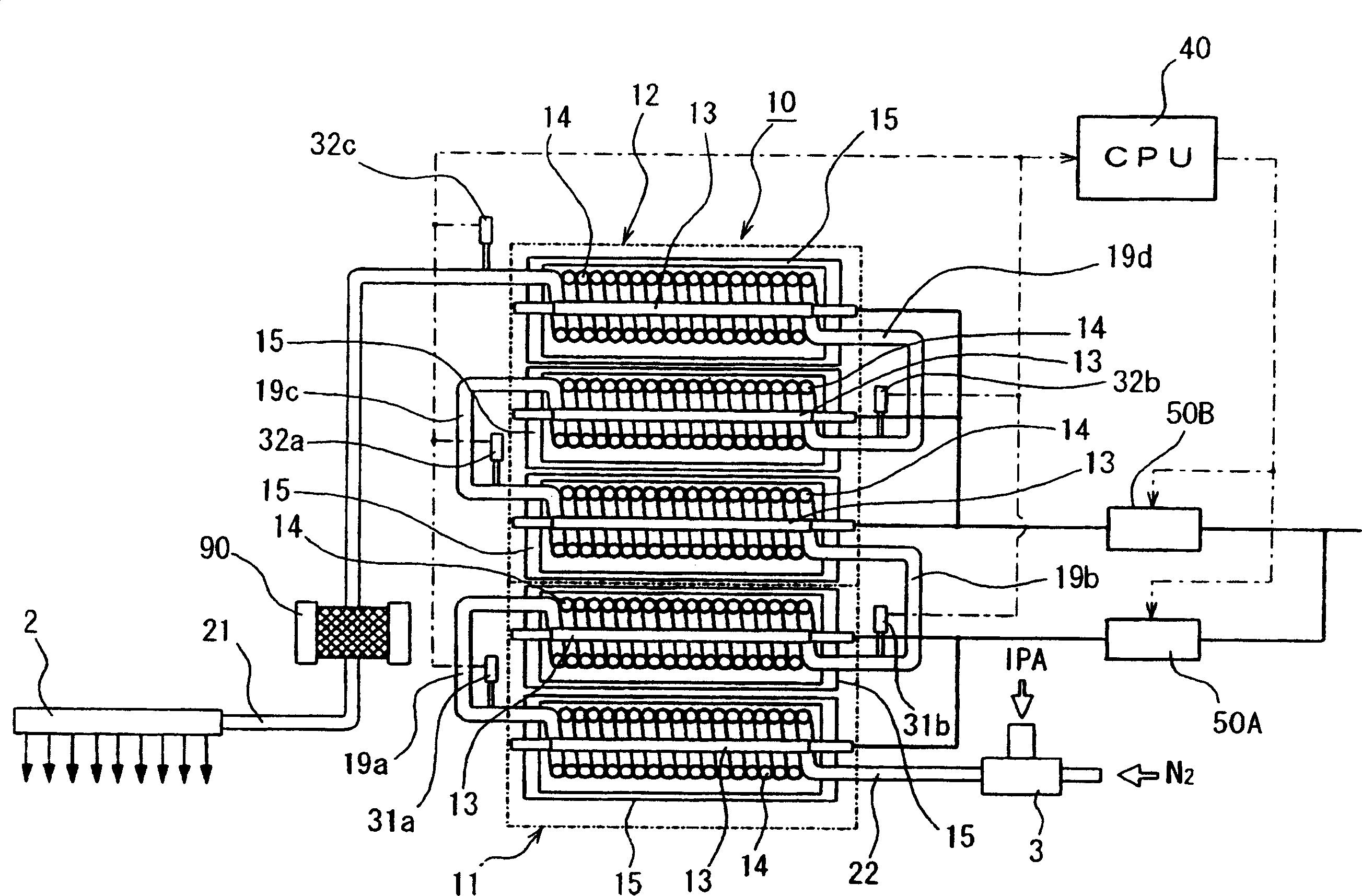
[0094] Fig. 6 is a schematic configuration diagram showing the overall structure of the above-mentioned washing and drying treatment system, Figure 7 It is a schematic sectional view showing the main part of the above-mentioned processing apparatus of the present invention.

[0095] The rinsing and drying processing system described above is provided with: a processing container 1 having a processing chamber 1a for accommodating a semiconductor wafer W (hereinafter referred to as a wafer W) as an object to be processed; (Jet) supply mechanism of steam for drying; steam generator 10 of the present invention generates IPA (isopropanol) and N 2 The steam of the mixed fluid of the gas; the two-fluid ...


PUM


Abstract

A vapor drying apparatus comprises a processing chamber (1a) adapted to contain semiconductor wafers (W); a supply nozzle (2) adapted to supply IPA vapor or N2 gas into the processing chamber (1a); a two-fluid nozzle (3) producing a mixed fluid of IPA and N2 gas; a vapor generating apparatus (10) adapted to produce IPA vapor by heating the mixed fluid; an N2 gas supply line (23) connected to the upstream side of the two-fluid nozzle (3); and a mixed fluid supply line (22) connected to the downstream side of the two-fluid nozzle. An open-and-close valve (V2) is provided on a branch line (25) connecting the N2 gas supply line and the mixed fluid supply line (22). First, N2 gas is supplied to the two-fluid nozzle (3) while IPA is supplied to the two-fluid nozzle (3) so as to produce the mixed fluid, followed by supplying it to the processing chamber (1a) so as to perform a first drying step. Subsequently, N2 gas is supplied to the processing chamber (1a) through the two-fluid nozzle (3) and the branch line (25) so as to perform a second drying step.

Description

technical field [0001] The present invention relates to a steam drying method, its device and its recording medium. Background technique [0002] For a long time, the following IPA drying technology has been known: make liquid or fluids that contain liquids such as liquid fluids, for example, make them dry in nitrogen (N 2 Gas) and other inert gases mixed with a mist organic solvent such as IPA (isopropanol) after the mixed fluid evaporates, and the evaporated gas is contacted with the object to be processed (dried body) to carry out drying treatment (for example, refer to the patent Literature 1). [0003] According to the above-mentioned steam drying method (device), the processing chamber that accommodates the object to be processed such as a semiconductor wafer (hereinafter referred to as a wafer) can be supplied by IPA and N 2 After the first drying is performed with steam composed of a gas mixture, only N is supplied to the processing chamber. 2 gas, the second dryi...

Claims


Application Information

Patent Timeline
Patent Type & Authority Applications(China)
IPC IPC(8): B01D53/26
CPCY02P80/15
Inventor 上川裕二小林和彦黑田信孝中岛干雄津田修
Owner TOKYO ELECTRON LTD
Why Eureka
Try Eureka