Dusting head for floor

A technology for cleaning head, floor

Inactive Publication Date: 2004-05-26
SANYO ELECTRIC CO LTD
View PDF2 Cites 13 Cited by
  • Summary
  • Abstract
  • Description
  • Claims
  • Application Information

AI Technical Summary

Problems solved by technology

In order to prevent scratches, for example, when a soft member such as rubber is used on the cover surface, there is a d

Method used


Image

  • Dusting head for floor
  • Dusting head for floor
  • Dusting head for floor

Examples


Example Embodiment

[0040] Hereinafter, embodiments of the present invention will be described in detail with reference to the drawings.
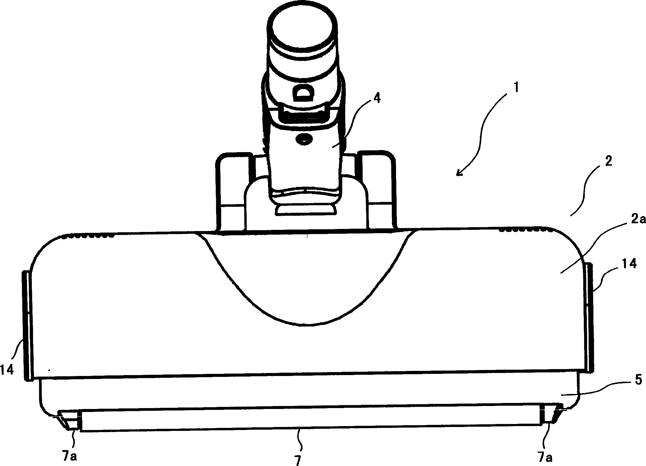
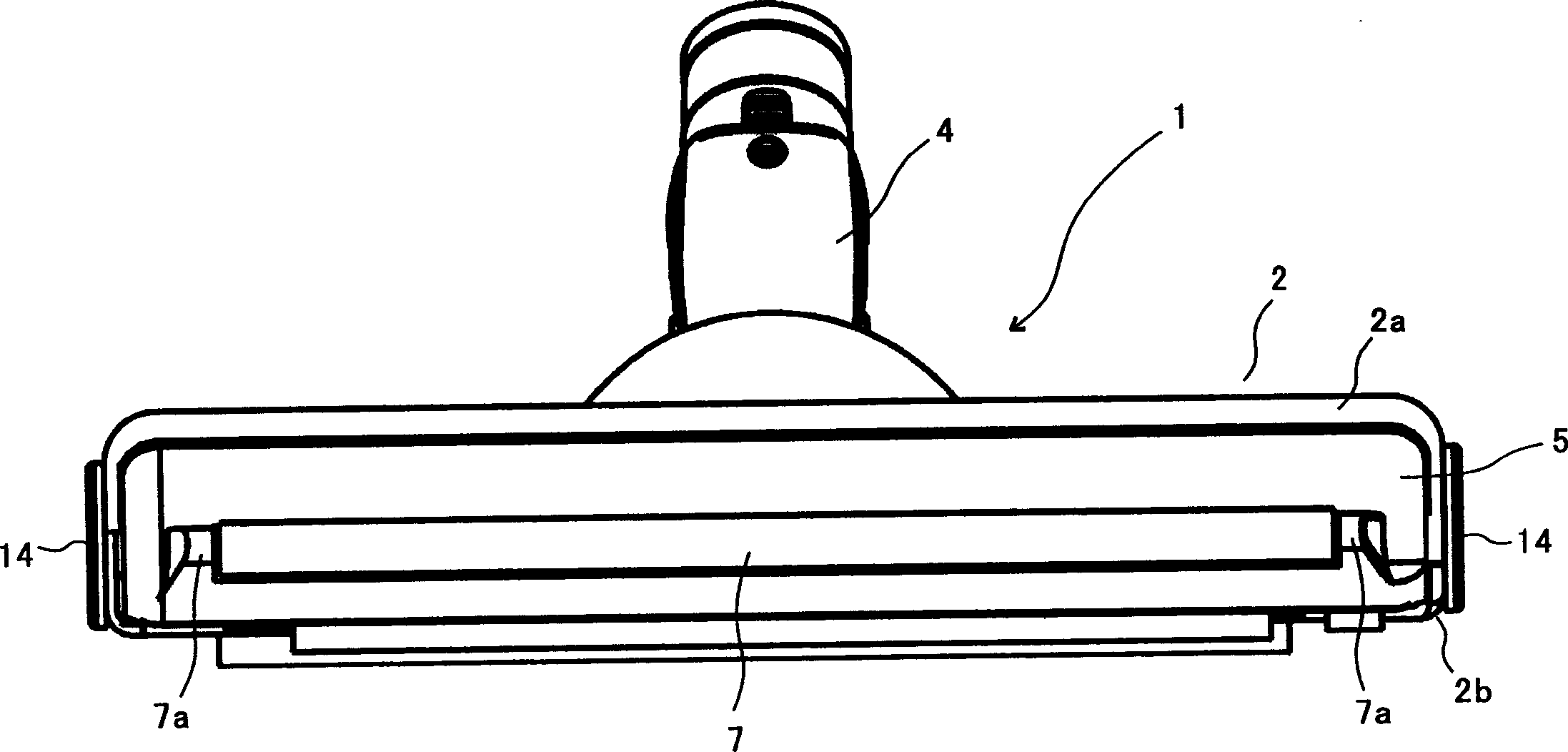
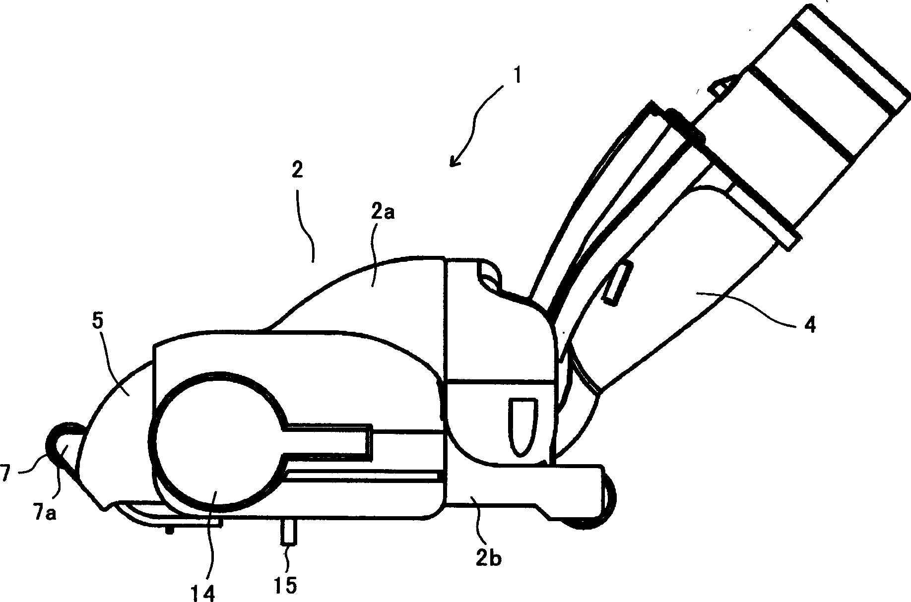
[0041] Figure 1~Figure 10 It is a figure which shows the structure and function of an Example of the vacuum cleaner for floors of this invention.

[0042] Figure 1~Figure 10 The floor cleaner head 1 shown is composed of a horizontally long cleaner head body box 2, a rotating brush 3, an elbow joint 4, and a cover 5. The cleaner head body box 2 is composed of an upper box 2a and a lower box 2b, and A suction port 6 with a wide range of openings is formed from the bottom to the front. The rotating brush 3 is rotatably supported on both ends in the longitudinal direction of the main body tube 2 of the cleaning head through a bearing. The elbow joint 4 is connected to the suction port 6 At the same time, it is rotatably installed on the rear side of the suction head body box 2 up and down, and the cover 5 forms the front wall of the suction head body box 2 while ope...


PUM


Abstract

The floor suction port 1 includes a suction hole 6 opening from a bottom face to at least a part of front face of a suction implement body case 2, a cover 5 which constitutes a front wall of the suction port body case 2 and is attached vertically rotatably to the suction port body case 2, and the cover 5 closes a front side part 6b of the suction hole 6 at the downward rotated position and opens the front side part 6b of the hole 6 at the upward rotated position rotated in contact with the wall face W. The cover 5 is provided with an abutting member (raised cloth 7b covering the outer peripheral surface of a roller 7) a soft and easily slidable at a part abutting on the wall face. To provide a floor suction port which can efficiently suck dust accumulating on a floor by a wall, is prevented from damaging wall faces and furniture and is smoothly rotatable. .

Description

technical field [0001] The present invention relates to a floor cleaning head of an electric vacuum cleaner, and more particularly to a floor cleaning head capable of efficiently sucking up dust accumulated on walls and the like. Background technique [0002] In the floor head of a general-purpose electric vacuum cleaner, the suction port is provided only on the bottom of the head body box, so it is difficult to clean places with standing obstacles such as walls or around the bottom of furniture. . [0003] Therefore, as a cleaning head capable of cleaning walls and the like, a cleaning head with the following structure has been proposed in the past. Or the sealing part moves upward or turns backward to attract dust on the wall (for example, refer to Patent Document 1 and Patent Document 2). [0004] There is also the following dust suction head, that is, the cross-sectional shape in the direction perpendicular to the rotation axis of the rotating brush is an arc shape wit...

Claims


Application Information

Patent Timeline
IPC IPC(8): A47L9/02A47L9/04
CPCA47L9/04A47L9/02
Inventor 小林利造福冈秀俊松本良昭
Owner SANYO ELECTRIC CO LTD
Why Eureka
Try Eureka