Solenoid operator and solenoid-operated switching device and control device for electromagnet

A technology of electromagnetic operation and switching device, which is applied to electric switches, electromagnets with armatures, and high-voltage/high-current switches, etc.

Active Publication Date: 2004-05-26
HITACHI IND EQUIP SYST CO LTD
View PDF1 Cites 6 Cited by
  • Summary
  • Abstract
  • Description
  • Claims
  • Application Information

AI Technical Summary

Problems solved by technology

[0008] However, there are still a large number of old-type analog relays as relays that output an opening command to the circuit breaker. When an electromagnetically operated switchgear is used on a switchboard equipped with analog relays, it is impossible to form an open circuit that requires a current of several amperes. the path of the command

Method used


Image

  • Solenoid operator and solenoid-operated switching device and control device for electromagnet
  • Solenoid operator and solenoid-operated switching device and control device for electromagnet
  • Solenoid operator and solenoid-operated switching device and control device for electromagnet

Examples


Embodiment Construction

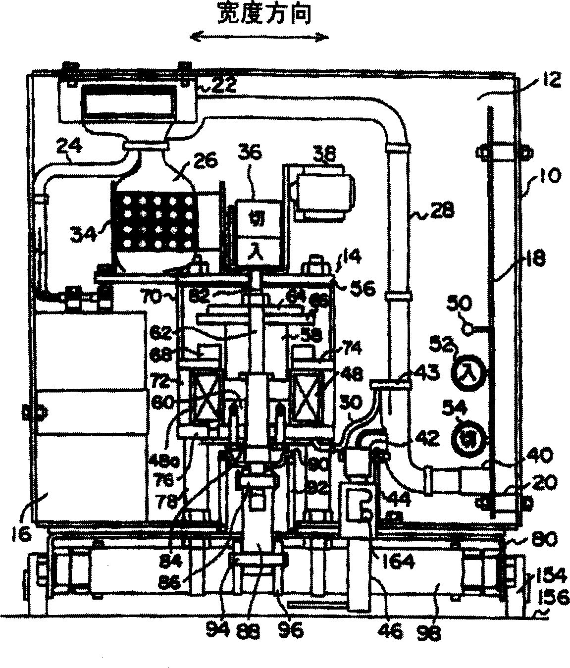
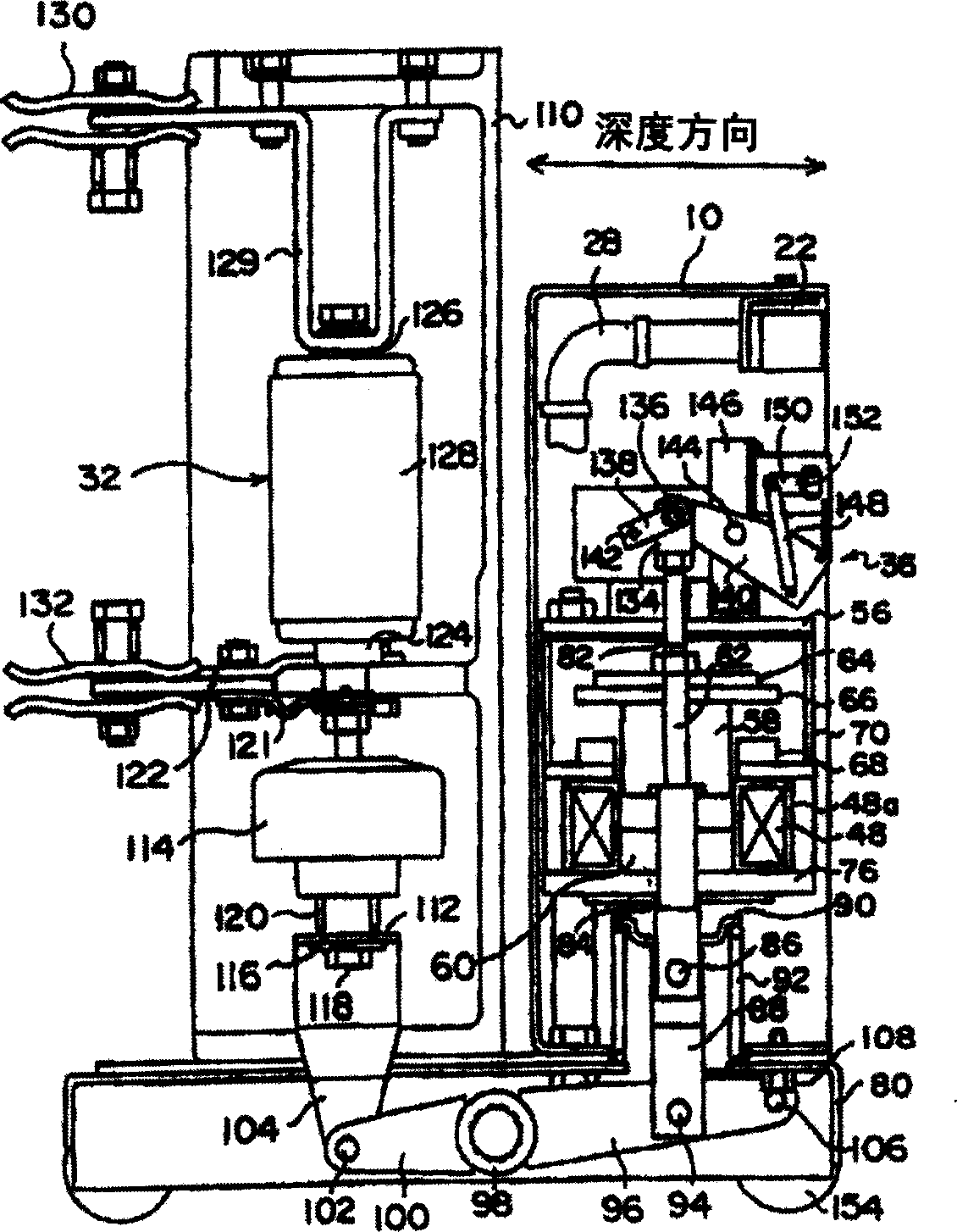
[0052] Next, an embodiment of the present invention will be described with reference to the drawings. figure 1 is a front view of the electromagnetic operating device of the present invention, figure 2 It is a side view of a solenoid-operated switchgear including a solenoid-operated device and a circuit breaker. exist figure 1 and figure 2 Among them, the electromagnetic operating device has a box-shaped casing 10, the casing 10 has an opening 12 on the front, and a front cover (omitted in the figure) is detachably fixed on the front of the casing 10. In the housing 10, a capacitor 16 and a control circuit board 18 are independently arranged with the electromagnet 14 as the center, the electromagnet 14 is fixed at the central position of the housing bottom with bolts and nuts, and the capacitor 16 and the control circuit board 18 are respectively fixed on on opposite sides of the enclosure. That is, the capacitor 16 is fixed on the left side of the housing 10 with bolt...


PUM


Abstract

The present invention permits a configuration for workability enhancement by mounting an electromagnet 14 under the center of a casing 10, mounting a capacitor 16 and a control circuit board 18 on either side of the electromagnet 14, mounting an auxiliary contact 34, an indicator plate 36 , and a counter 38 over the electromagnet 14, attaching the auxiliary contact 34, indicator plate 36, and counter 38 to a plate 56 to make them integral with the electromagnet 14, and rendering the capacitor 16 and control circuit board 18 removable from the front.

Description

technical field [0001] The present invention relates to an electromagnetic operating device, an electromagnetic operating switch device, and an electromagnet control device, and more particularly to an electromagnetic operating device and an electromagnetic operating switch device for operating a switch such as a circuit breaker by using electromagnetic force, and controls as a driving source for driving a switch. Solenoid control device for electromagnet drive. Background technique [0002] When operating a switch such as a circuit breaker, the electromagnetic force generated by the electromagnet can be utilized to operate (refer to the 2nd-4th pages of the patent document Japanese Patent Application Laid-Open No. 2002-217026, Figure 1-Figure 3 ). [0003] On the other hand, when driving the electromagnet, it is tested to install a capacitor that stores the electric energy used to excite the coil of the electromagnet, and to control the conduction direction of the current ...

Claims


Application Information

Patent Timeline
Patent Type & Authority Applications(China)
IPC IPC(8): H01H33/38H01F7/06H01F7/16H01F7/18H01H3/28
CPCH01H3/28H01H33/38H01H33/53
Inventor 薮雅人记井智之森田步中泽彰男川上久雄品川拓实杉野友启藤田康信中村满椎名贵嗣佐藤贞男小笠原健一矶野聪土屋贤治桥本利夫阿部圭介小山健二福地正博
Owner HITACHI IND EQUIP SYST CO LTD
Why Eureka
Try Eureka