Electrical connector with shutter

A technology of electrical connectors and switches, which is applied in the direction of connection, parts of connection devices, protective grounding/shielding devices of connection parts, etc., and can solve problems such as not including electrostatic discharge and damage to electronic circuits

Inactive Publication Date: 2004-05-26
TYCO ELECTRONICS JAPAN GK
View PDF2 Cites 10 Cited by
  • Summary
  • Abstract
  • Description
  • Claims
  • Application Information

AI Technical Summary

Problems solved by technology

[0008] However, like the electrical connector with a shutter according to Patent Document 2, the electrical connector with a shutter according to Patent Document 1 does not include measures for electrostatic discharge
Therefore, in such an electrical connector with a switch, although it is possible to prevent impurities from adhering to the contacts, electrostatic discharge may cause damage to the electronic circuit at the connection target.

Method used


Image

  • Electrical connector with shutter
  • Electrical connector with shutter
  • Electrical connector with shutter

Examples


Embodiment Construction

[0023] Embodiments of the present invention will be described below.

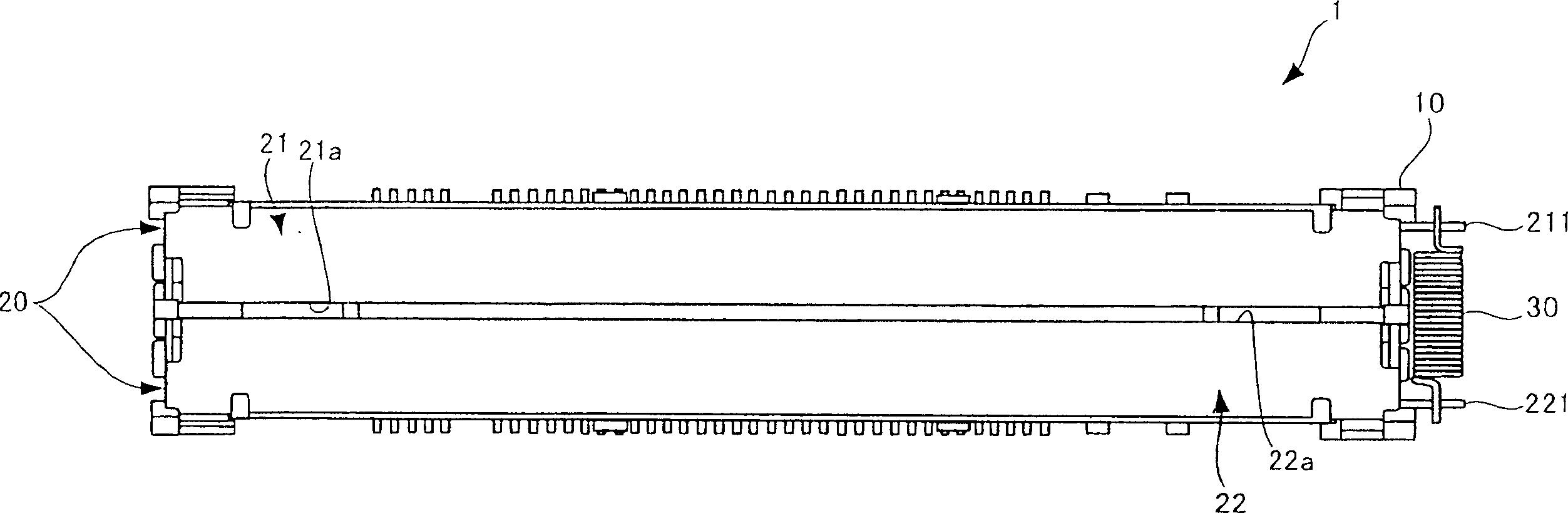
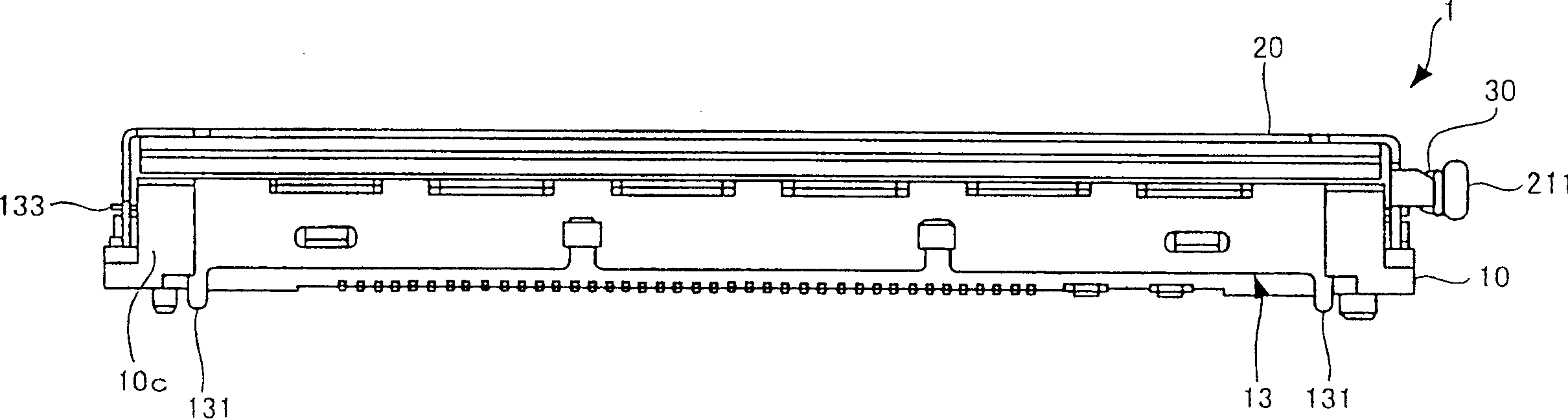
[0024] figure 1 A plan view showing an electrical connector with a shutter according to an embodiment of the present invention. figure 2 show figure 1 Front view of an electrical connector with a shutter.

[0025] figure 1 The electrical connector with a shutter 1 is a so-called SMT type electrical connector fitted to the surface of a circuit board. The electrical connector 1 with a shutter has a housing 10 , a pair of shutter elements 20 , and a spring element 30 . The case 10 has a junction in which a plurality of contacts are arranged in the longitudinal direction of the case 10 . The joint portion of the case 10 is covered with the pair of shutter elements 20, and is not in the figure 1 shown in . In the description that follows, use the figure 1 The side covered by the pair of shutter elements 20 of the electrical connector 1 will be referred to as the front side, and the opposite side will be...


PUM


Abstract

To prevent the adhesion of the foreign matters to the contacts and also to prevent damage to the electronic circuit of the connected equipment by the electrostatic discharge, in the electric connector with a shutter equipped with a housing having an engagement part arranged with a plurality of contacts and a pair of shutter members covering the engagement part of the housing in free opening and shutting. The pair of shutter members are made of metal and are energized in the direction of the edges approaching each other, and in the state of the edges approached together, cover the engaging part, and release the engagement part when the edges are separated. The housing is equipped with a shield member 13 that surrounds the surroundings of the housing and has a protrusion 133 that is clipped by the pair of shutter members when the edges come close.

Description

technical field [0001] The present invention relates to an electrical connector with a shutter provided with a housing having a joint having a plurality of contacts provided therein and a pair of shutter elements, the shutter elements covering the housing joints for free opening and closing. Background technique [0002] In the case of an electrical connector with a mating portion having a plurality of contacts disposed therein and fitted onto the mating connector, the mating portion is exposed if the mating connector is not fitted into the mating portion. When the joint portion is fitted to the joint connector, foreign matter may adhere to the contacts, thereby possibly interrupting the electrical connection. Therefore, there has been proposed an electrical connector having a shutter having a pair of shutter elements covering joints so as to be freely opened and closed (see Patent Document 1). The electrical connector with a shutter described in Patent Document 1 has a pa...

Claims


Application Information

Patent Timeline
Patent Type & Authority Applications(China)
IPC IPC(8): H01R13/52H01R13/453H01R13/648
CPCH01R13/4536H01R13/6485
Inventor 笹目直孝桥本信一
Owner TYCO ELECTRONICS JAPAN GK
Why Eureka
Try Eureka