Working unit for programme-controlled milling and boring machines

A technology of power head, drilling and milling machine, applied in the field of power head, can solve the problem of high cost of positioning and swing head technology, and achieve the effect of high cutting power

Inactive Publication Date: 2004-06-02
DECKEL MAHO PFRONTEN GMBH
View PDF3 Cites 7 Cited by
  • Summary
  • Abstract
  • Description
  • Claims
  • Application Information

AI Technical Summary

Problems solved by technology

In addition, the technical cost required to position the oscillating head is high

Method used


Image

  • Working unit for programme-controlled milling and boring machines
  • Working unit for programme-controlled milling and boring machines
  • Working unit for programme-controlled milling and boring machines

Examples


Embodiment Construction

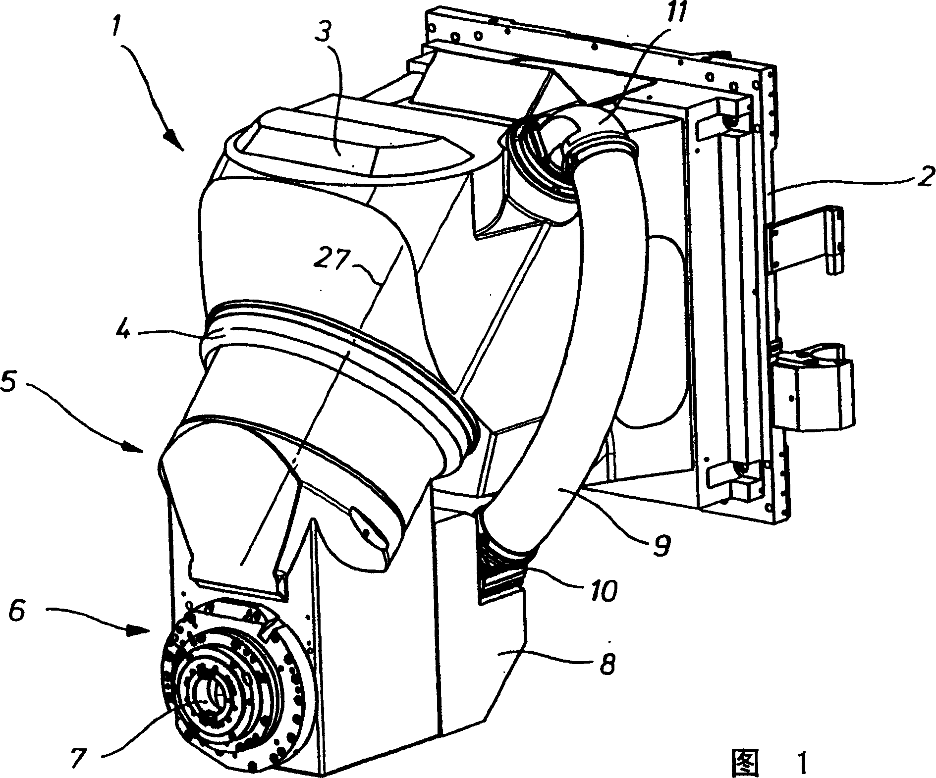
[0014] It can be seen from Fig. 1 that the power head has a cornered head seat 1, which includes a vertical, rearward plate-shaped or frame-shaped support structure 2, a large-volume middle part 3, and a 45° forward and downward slope. Hollow cylindrical shell 4. In the headstock 1, a swivel head 5 is mounted rotatably about the central axis 27 of the hollow-cylindrical housing projection 4, which is fixed rigidly at an angle of 45° to the central axis 27 of the housing projection 4 on the swivel head side. There is a spindle head 6. In the transverse direction of the spindle head 6, a work spindle 7 is supported. By means of an adapter 10, a flexible tube 9 is pivotably connected to the box-shaped rear part 8 of the spindle head 6, the upper end of which is connected to the middle part 3 of the headstock 1 via a rotatable tube elbow 11. connect.

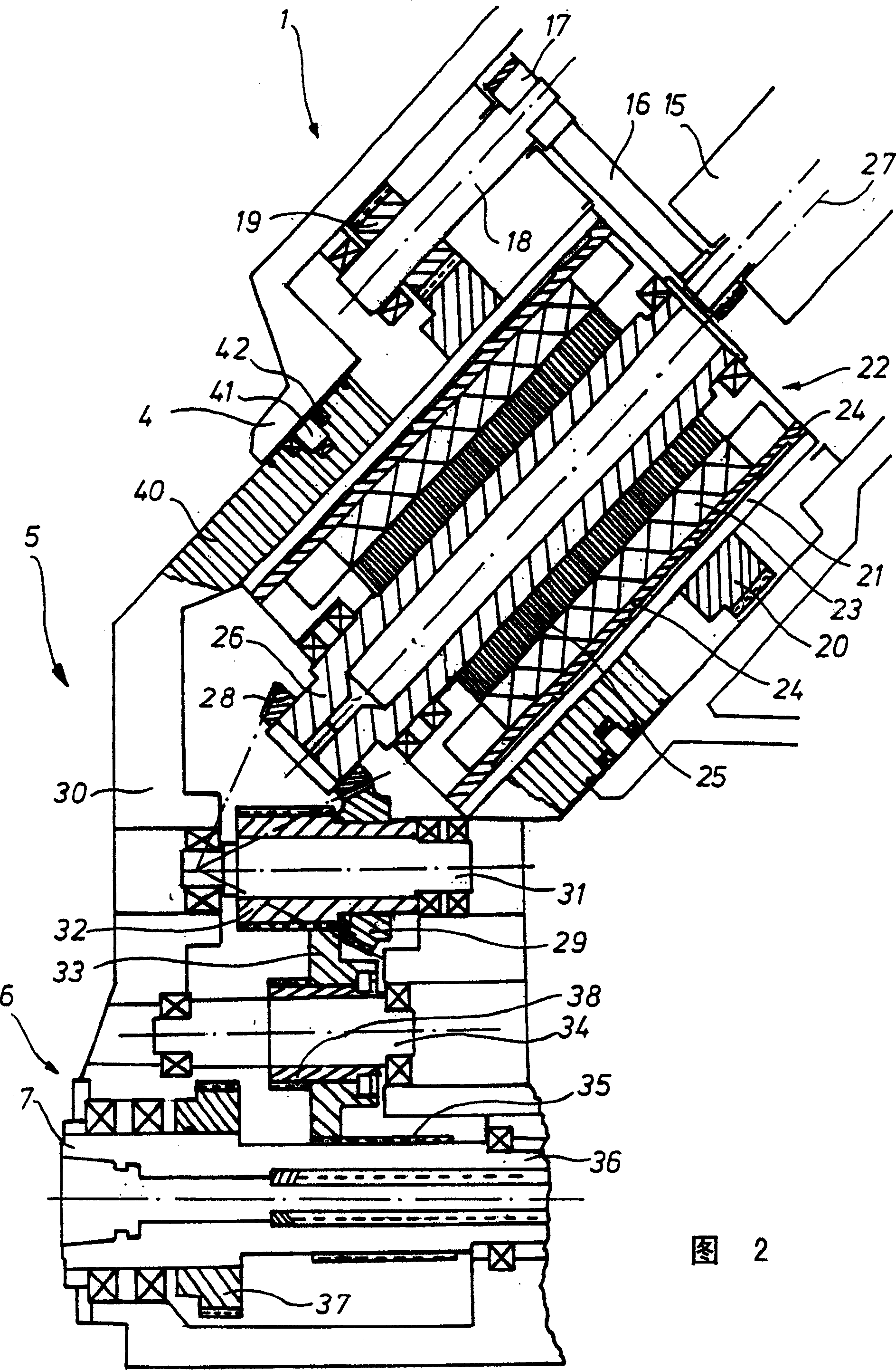
[0015] Figure 2 shows a schematic vertical cross-sectional view of the internal functional parts of the power head of the prese...


PUM


Abstract

The pivot head (5) includes a cylindrical casing section (40) extending coaxial to the pivot head rotation axis (27) and having a spindle motor (22) secured inside it. The head support (1) includes a casing extension (4) in which the cylindrical casing section is rotatably mounted. The head support can be moved along various coordinate axes and contains a 45 deg. rotation axis extending downwards in the forwards direction. The pivot head is mounted on one of the faces of the head support and is rotatable about the 45 deg. axis via a motor. A spindle head (6) fixed to the pivot head is connected to a spindle (7) extending at an angle of 45 deg. relative to the pivot head rotation axis. The spindle motor extends coaxial to the pivot head rotation axis. An angle gear mechanism (28, 29) for the spindle drive is located inside the pivot head.

Description

technical field [0001] The invention relates to a power head of a program-controlled drilling and milling machine, which comprises: a headstock movable along multiple coordinate axes, which has a rotation axis pointing forward and downward at an angle of 45°; a headstock capable of rotating around the 45° rotation axis The oscillating head that is arranged on the end side of headstock; One is fixedly installed on the oscillating head and has the spindle head of a working spindle, and the direction of the axis of this working spindle forms 45 ° angle with this 45 ° rotation axis. Background technique [0002] In order to selectively process workpieces horizontally or vertically under the same clamping conditions, power heads with an oscillating or rotating body which carry a working spindle and allow its axial Oriented horizontally and vertically. [0003] DE4402084A has described this kind of power head, and it has a supporting housing movable on the frame, and on its obliq...

Claims


Application Information

Patent Timeline
Patent Type & Authority Applications(China)
IPC IPC(8): B23B39/02B23B47/00B23C1/12B23P23/00B23P23/02B23Q1/00B23Q1/25B23Q1/54F16H1/06F16H1/12F16H57/02
CPCB23Q1/0036Y10T409/308512Y10T29/5107B23Q1/54Y10T408/93Y10T409/307672
Inventor A·盖斯勒
Owner DECKEL MAHO PFRONTEN GMBH
Why Eureka
Try Eureka