Feed system for straight line synchronous motor type vehicle

A feeding system and linear synchronization technology, applied in the field of feeding systems, can solve problems such as large capacity

Inactive Publication Date: 2004-06-09
CENTRAL JAPAN RAILWAY COMPANY
View PDF0 Cites 0 Cited by
  • Summary
  • Abstract
  • Description
  • Claims
  • Application Information

AI Technical Summary

Problems solved by technology

[0010] However, during normal driving, the above-mentioned section requiring a large driving force is largely in charge of the specific inverter device, so other inverter dev...

Method used


Image

  • Feed system for straight line synchronous motor type vehicle
  • Feed system for straight line synchronous motor type vehicle
  • Feed system for straight line synchronous motor type vehicle

Examples


no. 1 Embodiment

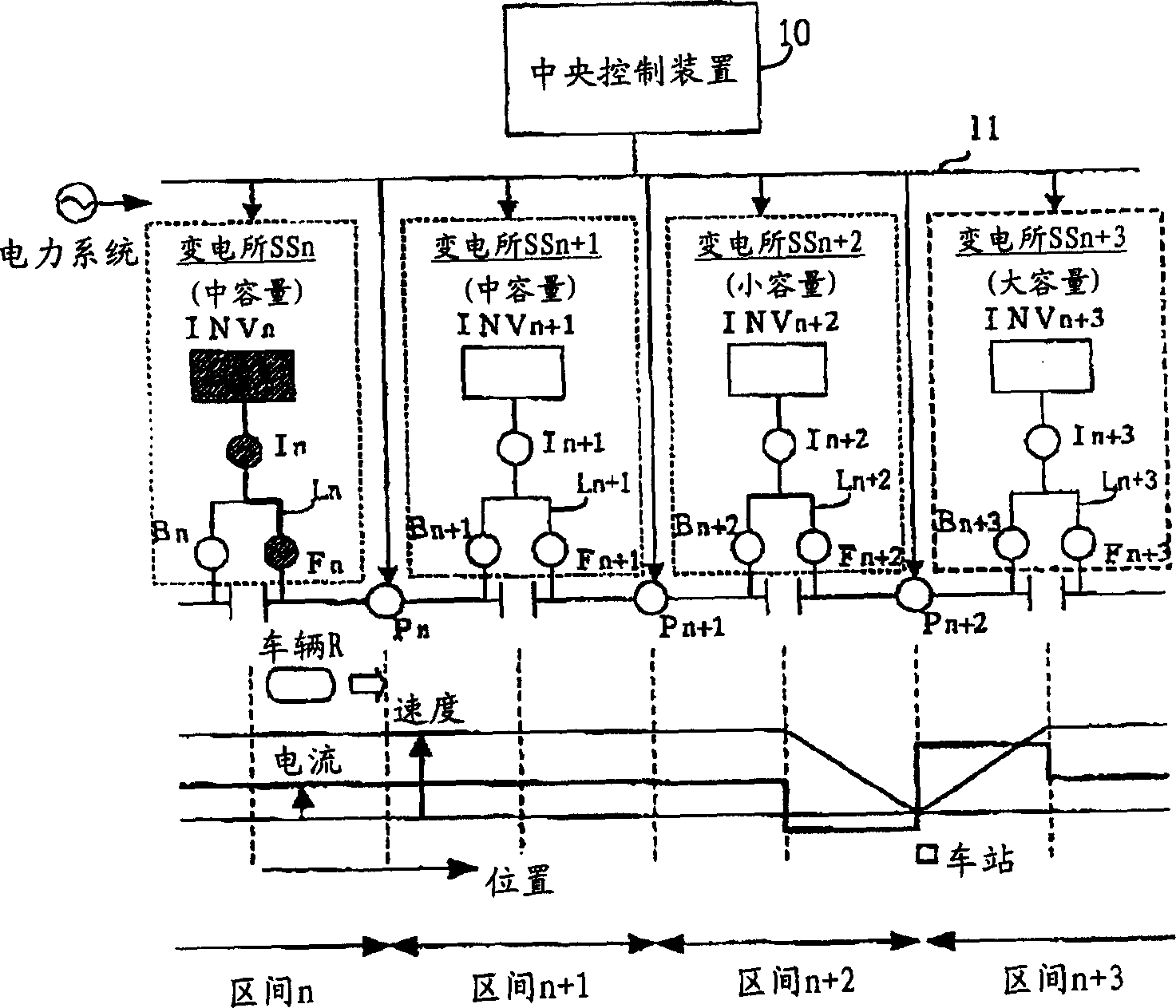
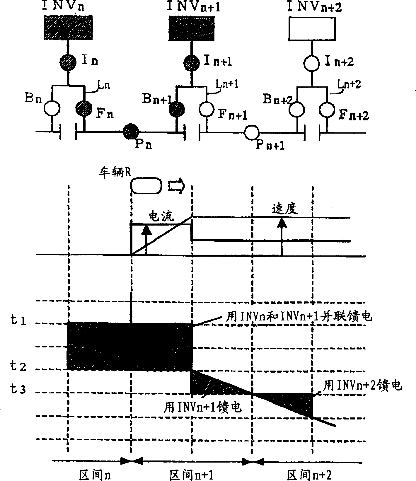
[0036] figure 1 Showing the schematic structure of the feed system of the LSM type vehicle according to the first embodiment of the present invention, figure 2 The feed control method of this embodiment is shown. Among them, the basic structure and usage of the feeding equipment in the feeding system Figure 5 What has been described is substantially the same, so the same reference numerals (symbols) are assigned to the same structures, and descriptions thereof are omitted.

[0037] like figure 1 As shown, in the power feeding system of this embodiment, in each substation SSn~SSn+3..., the three-phase AC power received from the power system is temporarily converted into DC power by a converter not shown in the figure, and then each inverter Inverter devices INVn to INVn+3 convert the DC power into three-phase AC power having a frequency and magnitude necessary to drive the LSM vehicle R, and supply it to each propulsion coil through each feeder line Ln to Ln+3. On the fe...

no. 2 Embodiment

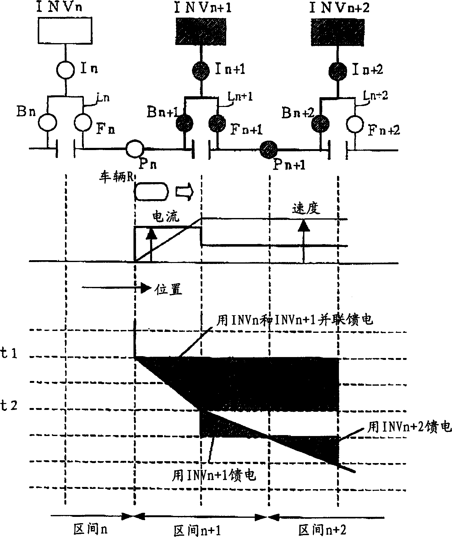
[0045] In the above-mentioned first embodiment, an example was shown in which parallel power feeding control is performed within a section of a single line (up or down), but the power feeding system of this embodiment can perform parallel power feeding between double lines (up and down). Figure 4 Shows the feed control method of this embodiment, corresponding to the one described in the first embodiment figure 2 , image 3 . Here, the basic configuration of the feeding equipment and the principle of the feeding method in this feeding system are substantially the same as those of the first embodiment, so the same reference numerals (symbols) are assigned to the same configurations and their descriptions are omitted.

[0046] The feeder system of this embodiment includes feeder lines RLn-RLn+3 for upstream and feeder lines LLn-LLn for downstream in substations SSn-SSn+3 in each section n-n+3... +3 inverter devices (RINVn, LINVn) to (RINVn+3, LINVn+3) respectively supplying e...


PUM


Abstract

In this feeder system, the inverters INVn-INVn+3, etc., of a substation installed in intervals n-n+3, etc., respectively, have capacitances individually set for the intervals to enable normal travel of the LSM vehicle so that the inverters do not require unnecessarily large capacitances. When power for driving becomes insufficient for an interval due to some reason, control is executed for feeding the power required for the LSM vehicle R to travel through parallel feeding by using the neighboring inverters so that the driving force required for the LSM vehicle is assured.

Description

technical field [0001] The present invention relates to the feed system of the LSM type vehicle using the primary linear synchronous motor on the ground. Background technique [0002] Conventionally, in floating railways, vehicles have been driven using a ground primary linear synchronous motor (LSM) system in which superconducting magnets are placed on the vehicle side and propulsion coils are placed on the ground side. Vehicles employing this LSM system (LSM vehicles) generate attractive and repulsive forces between the superconducting electromagnets on the vehicle side and the propulsion coils on the side wall of the track by supplying power to the propulsion coils through the feeder lines from the substations installed along the track. , to get its driving force. At this time, the speed of the LSM vehicle is determined by the frequency of the voltage and current supplied to the propulsion coil. This frequency adjustment is performed by the inverter device of the substa...

Claims


Application Information

Patent Timeline
IPC IPC(8): B61B13/08B60L13/10B60M3/04B60M7/00
CPCY02T10/7241Y02T90/16Y02T10/72
Inventor 池田春男北野淳一小野基治
Owner CENTRAL JAPAN RAILWAY COMPANY
Why Eureka
Try Eureka