

Planar display with touch panel
A flat-panel display, touch panel technology, applied in the direction of instruments, chemical instruments and methods, data processing input/output processes, etc., can solve the problems of increasing the weight of the display module, the depth of field, and increasing the thickness and weight of the display module.
- Summary
- Abstract
- Description
- Claims
- Application Information
AI Technical Summary
Problems solved by technology
Method used
Image

Examples
Embodiment Construction
[0043] Some embodiments of the invention are described in detail below. However, the invention may also be practiced broadly in other embodiments than those described in detail, and the scope of the invention is not limited only by the appended claims.
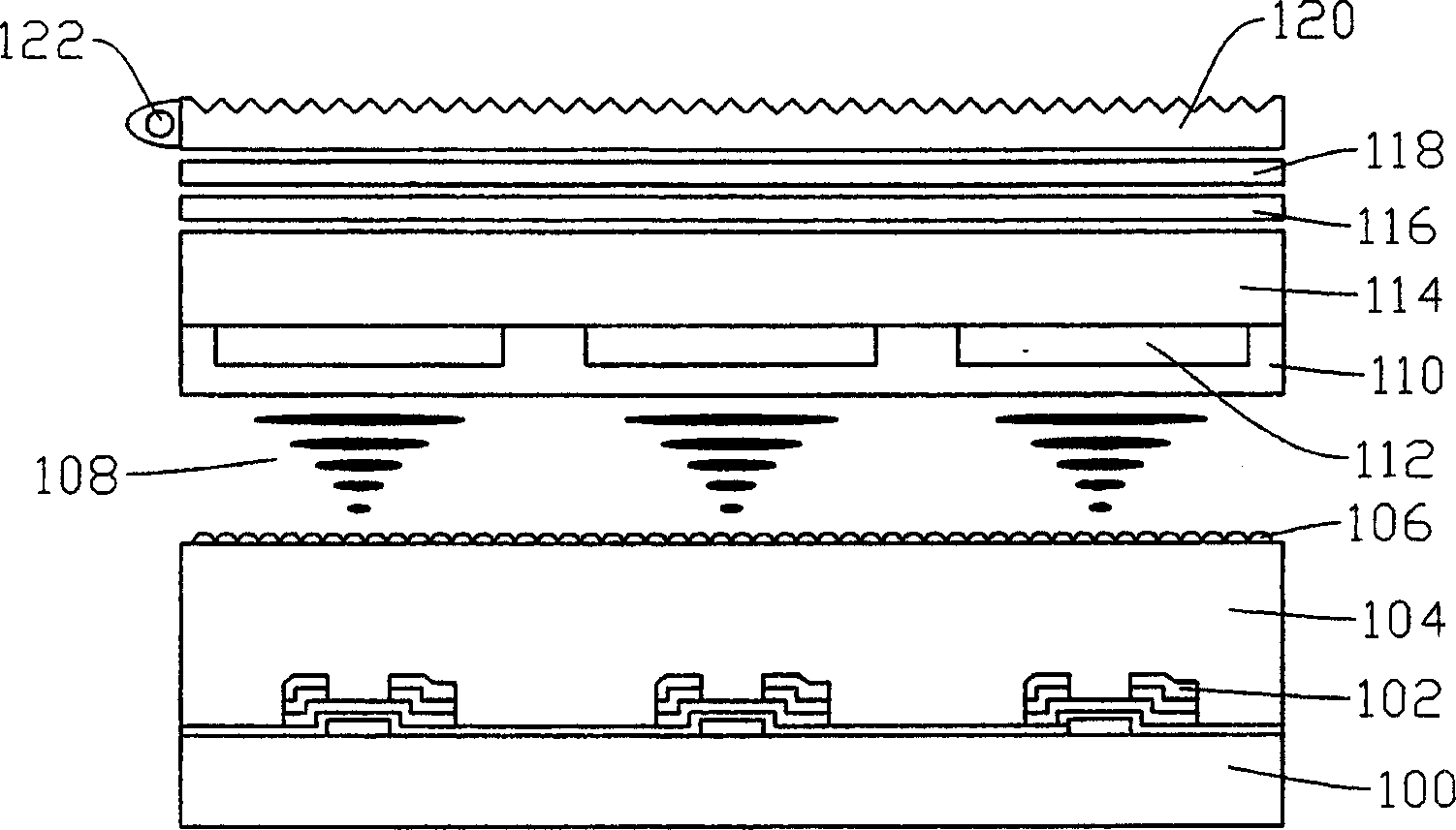
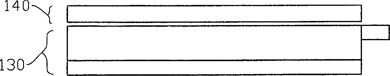
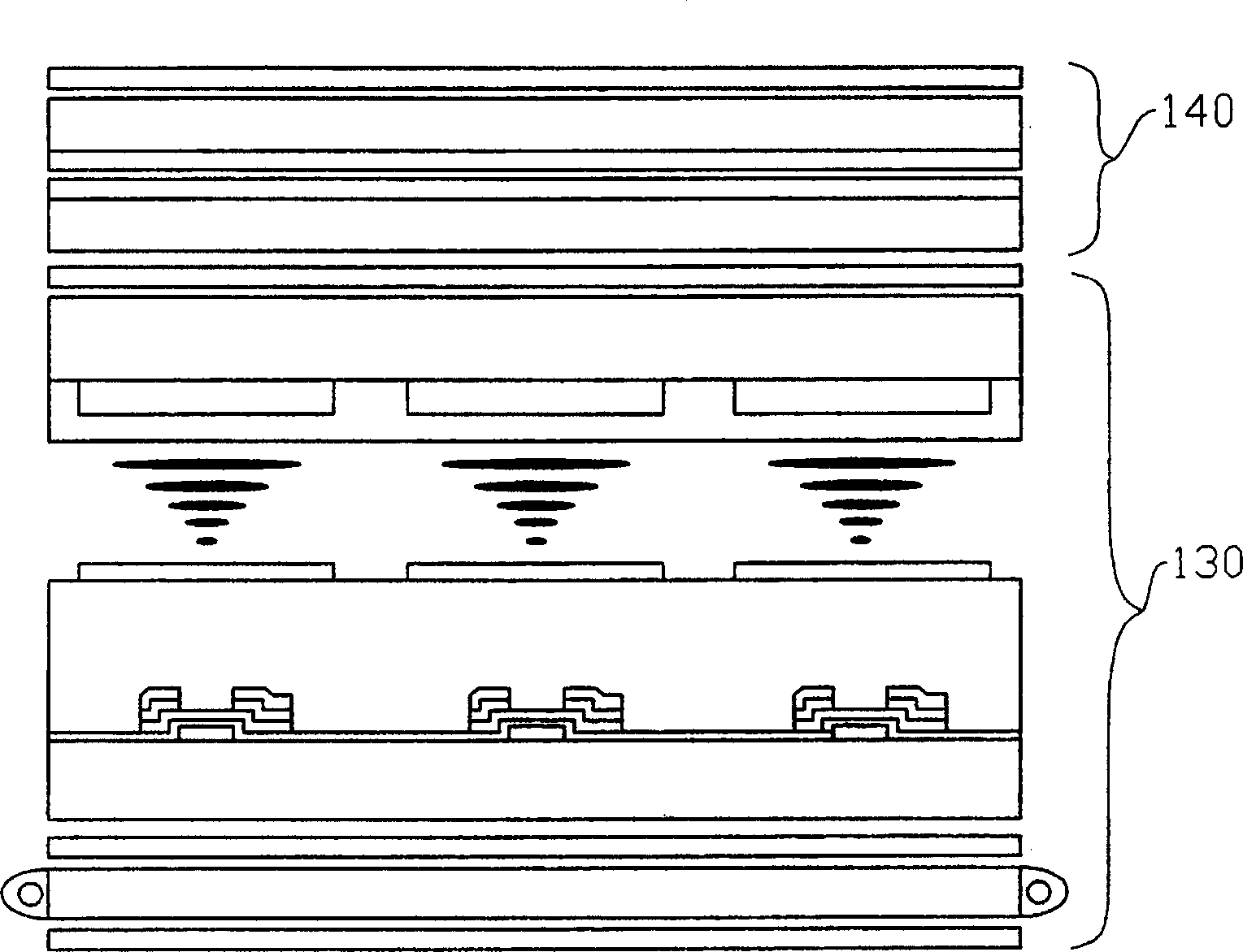
[0044] The present invention mainly provides a flat panel display with a touch panel, including a reflective liquid crystal display and a touch panel. The above-mentioned reflective liquid crystal display at least includes a transparent substrate and a light source located on one end surface of the above-mentioned transparent substrate, wherein the above-mentioned transparent substrate is a light guide plate, and its material can be a plastic substrate. The above-mentioned touch panel is located on the aforementioned reflective liquid crystal display, and at least includes a first transparent conductive layer on the aforementioned transparent substrate, an adhesive layer located on the aforementioned first transparent conducti...
PUM
 Abstract
Description
Claims
Application Information