
Needle set

A needle group and needle butt technology, which is applied in the field of needle group of knitting machines, can solve problems such as the collision of needle butts and cam parts, and achieve the effect of preventing damage

Active Publication Date: 2004-06-30
GROZ BECKERT KG
View PDF0 Cites 1 Cited by
  • Summary
  • Abstract
  • Description
  • Claims
  • Application Information

AI Technical Summary

Problems solved by technology

But sometimes due to the wrong control of the triangular parts and other accidental events, there will be collisions between the butt and the triangular parts

Method used


Image

  • Needle set
  • Needle set
  • Needle set

Examples


Embodiment Construction

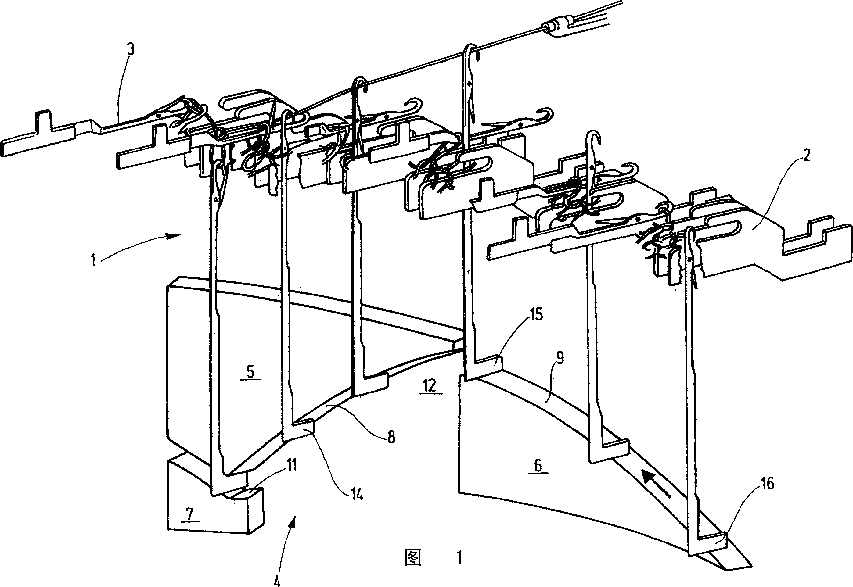
[0023] FIG. 1 shows a needle group 1 which, together with sinkers 2 and further needles 3 arranged transversely to said first needle 1, forms a knitting system of a knitting machine. Needle 1 is driven by a cam 4 formed by cam segments 5,6,7. These triangular parts define a triangular groove 12 with guide surfaces 8 , 9 , 11 . This slot is used to drive the butts 14 , 15 , 16 of the needle 1 into the triangular slot 12 .

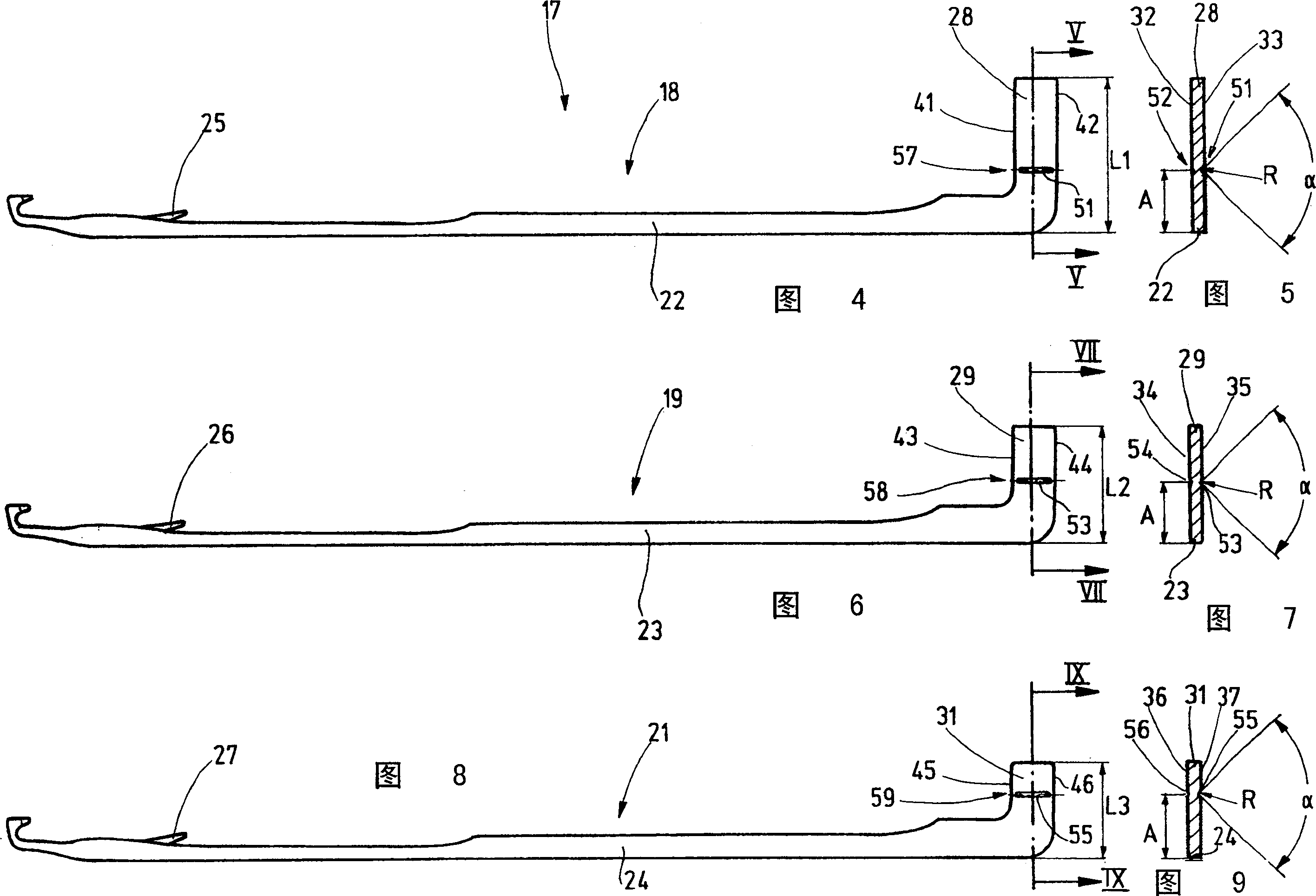
[0024] These needles 1 form a needle set 17 of three needles, indicated by needles 18 , 19 , 21 shown in FIGS. 4 , 6 and 8 . These needles 1 in FIG. 1 comprise needles 18 , 19 , 21 of needle set 7 , for example. These needles 18, 19, 21 have a needle bar 22, 23, 24 respectively, the end of which has a hook. The needles 18 , 19 , 21 are designed, for example, as latch needles, so that a pivotable latch next to each hook opens and closes in a controlled manner.

[0025] Needle shanks 22, 23, 24 of needles 18, 19, 21 have a needle butt 28, 29, 31 respective...


PUM


Abstract

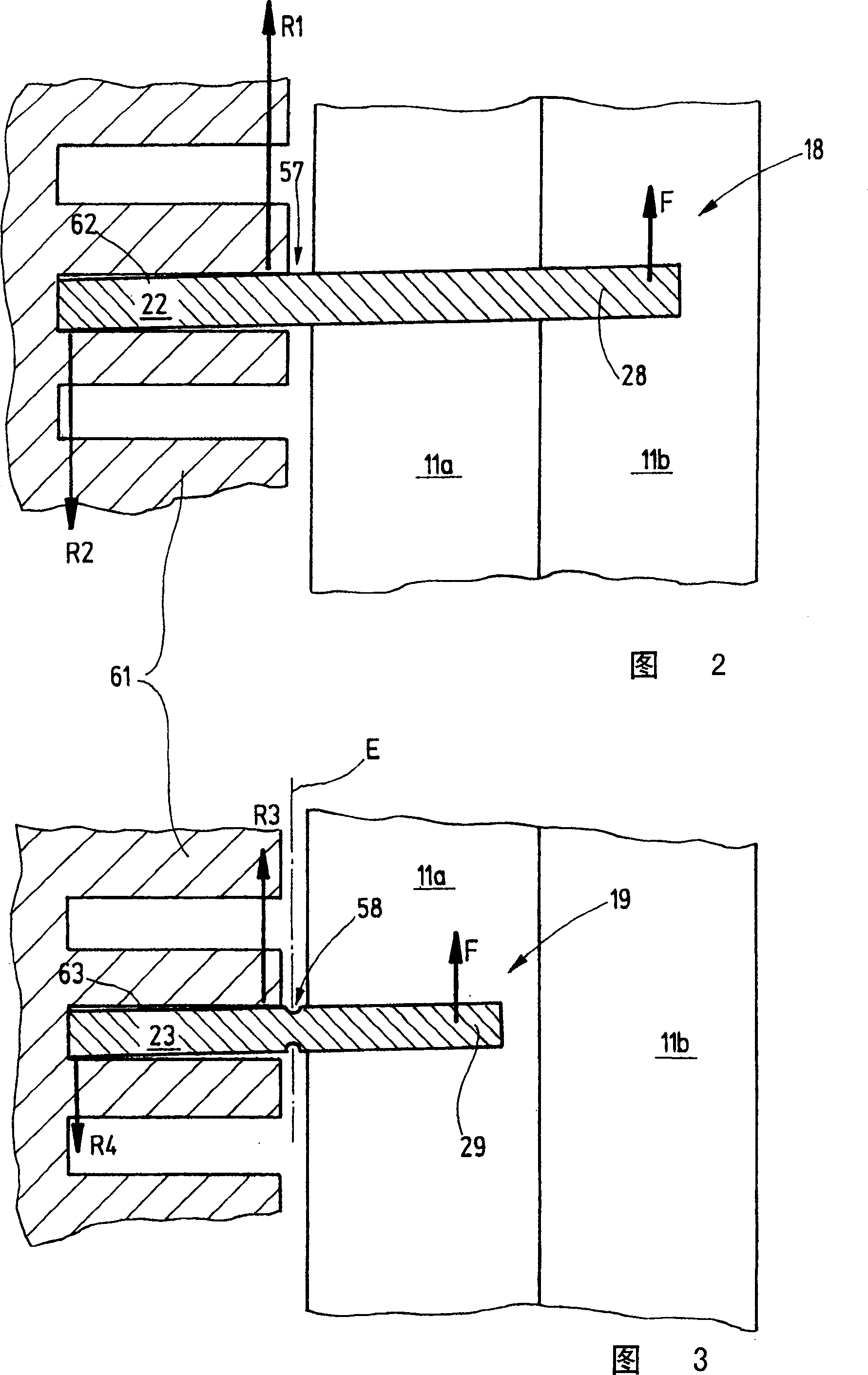
The needles (18, 19) of a needle set (17), which substantially agree in their geometry, have butts (28, 29) of different lengths, which have a predetermined breaking point (57, 58). The predetermined breaking points are differently embodied, so that the breaking torques of the butts (28, 29) of the needles (18, 19), which are a part of the set (17), are different. By means of this it is possible, on the one hand, to assuredly prevent damage to the knitting machine, but on the other hand to assure the dependable operation of the needles.

Description

technical field [0001] The invention relates to a needle set, in particular for a knitting machine. Background technique [0002] A knitting machine needle has an elongated shank, usually of flat material, from which one or more butts protrude laterally. The butt is used to make the needle move linearly in the needle groove. For this, they are connected with so-called triangles. Linear movement of the needles is caused by the relative movement of the cams to the needles or the needle beds accommodating them and the butts move through a cam slot. Generally speaking, these functions are absolutely reliable. But sometimes due to the wrong control of the triangle parts and other accidental events, collisions between the butts and the parts of the triangle will occur. Collisions must be avoided to cause damage to the knitting machine components, especially the cams or needle beds. The needle bed consists of a multi-part solid body into which a plurality of closely spaced gro...

Claims


Application Information

Patent Timeline
IPC IPC(8): D04B35/04D04B35/02
CPCD04B35/02
Inventor U·施廷格尔B·哈根斯E·费伦巴赫
Owner GROZ BECKERT KG
Learn More