
Area light source device and light board thereof

A light guide plate and surface light source technology, applied in optics, nonlinear optics, diffuser elements, etc., can solve problems such as uneven distribution of light energy and uneven energy distribution of light sources, and achieve good uniformity

Inactive Publication Date: 2004-06-30
HONG FU JIN PRECISION IND (SHENZHEN) CO LTD +1
View PDF0 Cites 7 Cited by
  • Summary
  • Abstract
  • Description
  • Claims
  • Application Information

AI Technical Summary

Problems solved by technology

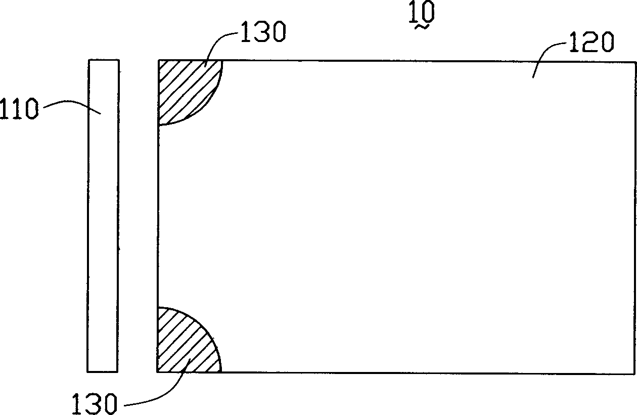
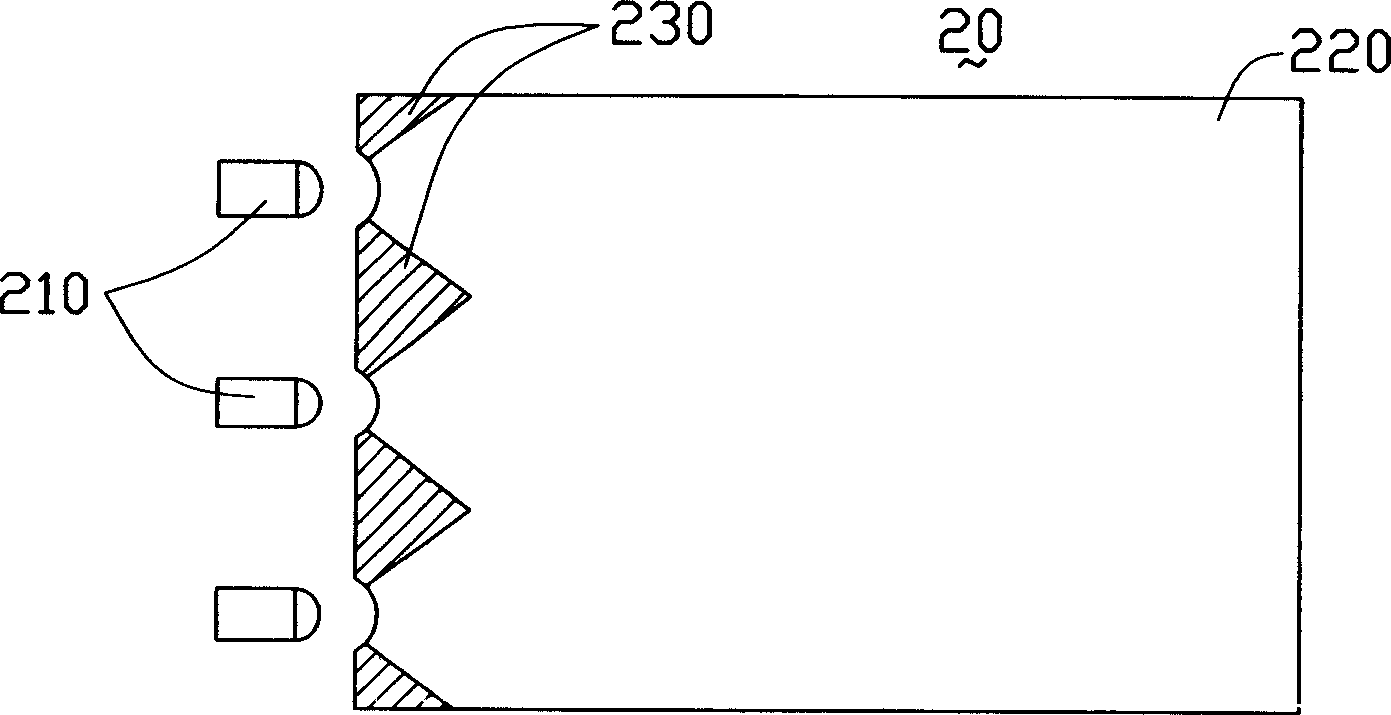
[0006] In order to solve the technical problem of uneven distribution of light energy emitted by the surface light source device in the prior art due to uneven energy distribution of the light source, the present invention provides a surface light source device with uniform light output

Method used


Image

  • Area light source device and light board thereof
  • Area light source device and light board thereof
  • Area light source device and light board thereof

Examples


Embodiment Construction

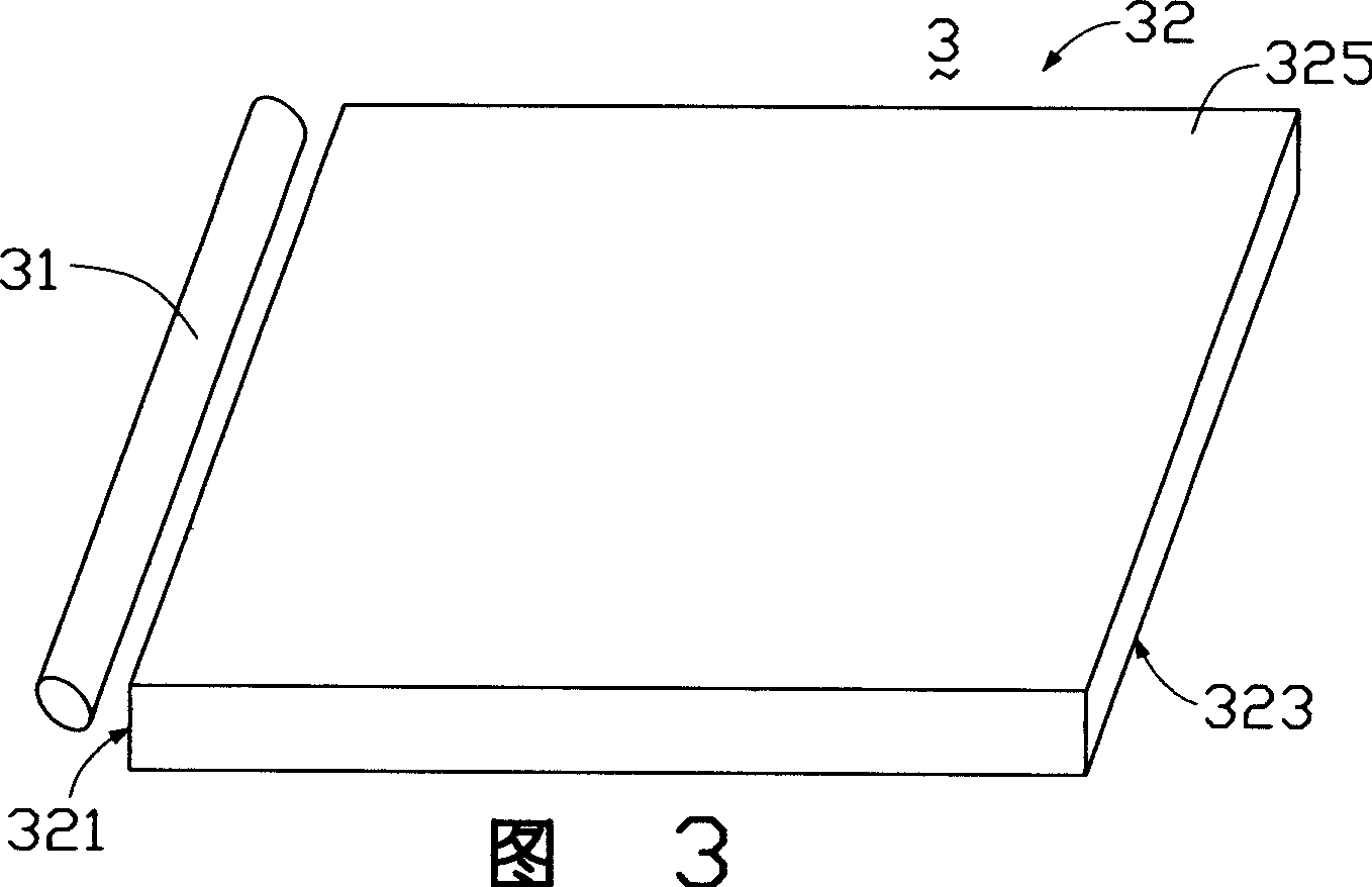
[0017] Please refer to Figure 3 and Figure 4 The surface light source device 3 according to the first embodiment of the present invention includes a light guide plate 32 and a light source 31 disposed on one side of the light guide plate 32 . The light guide plate 32 includes a light incident surface 321 for receiving light, a light exit surface 325 guiding light to exit and intersecting the light incident surface 321 , and a bottom surface 323 opposite to the light exit surface 325 . The light source 31 is a linear light source disposed on the light incident surface 321 side of the light guide plate 32 , such as a cold cathode fluorescent lamp. Because the luminance distribution of the light source 31 itself is uneven, the luminance distribution in the middle part is stronger and uniform, and the luminance distribution at the two ends is weaker and the luminance gradually increases from the two ends to the middle part, so the light incident on the light guide plate adjacent ...


PUM


Abstract

The invention is a kind of surface source device for liquid monitor. The device comprises a light board and at least a source. The light board at least comprises an entrance face for receiving beams, a light exit face intersecting with the entrance face and a back face opposite to the entrance. The light house is at one side of the entrance face. The back face has a round or rectangular scattering spot.

Description

【Technical field】 [0001] The invention relates to a surface light source device and a light guide plate used in the surface light source device. 【Background technique】 [0002] Since the liquid crystal display panel itself does not have luminous properties, a surface light source device is required to provide it with uniform planar light to obtain a good visual effect. [0003] The surface light source device in the prior art includes a light source and a light guide plate. The light source is arranged relative to the light incident surface of the light guide plate. The light guide plate guides the transmission direction of the light beam emitted from the light source, and converts the line light source or point light source into a surface light source to emit. A plurality of scattering points are distributed on the bottom surface of the light guide plate to destroy the total reflection condition of the light beam transmitted inside the light guide plate, and make it diffuse...

Claims


Application Information

Patent Timeline
Patent Type & Authority Applications(China)
IPC IPC(8): G02B5/02G02F1/13357
Inventor 吕昌岳陈杰良余泰成
Owner HONG FU JIN PRECISION IND (SHENZHEN) CO LTD
Learn More