
Method for producing light guide plate and mold

A manufacturing method and technology for manufacturing molds, which are applied in the field of light guide plate manufacture and molds, can solve the problems of poor uniformity of wedge-shaped or dish-shaped light guide plates, and achieve the effects of uniform shape, good uniformity, and good optical uniformity

Inactive Publication Date: 2004-07-14
HONG FU JIN PRECISION IND (SHENZHEN) CO LTD +1
View PDF0 Cites 13 Cited by
  • Summary
  • Abstract
  • Description
  • Claims
  • Application Information

AI Technical Summary

Problems solved by technology

[0007] In order to solve the defect of poor uniformity of the wedge-shaped or dish-shaped light guide plate made by the manufacturing method of the light guide plate in the prior art, the present invention provides a method for manufacturing a wedge-shaped or dish-shaped light guide plate with good uniformity

Method used


Image

  • Method for producing light guide plate and mold
  • Method for producing light guide plate and mold
  • Method for producing light guide plate and mold

Examples


no. 1 approach

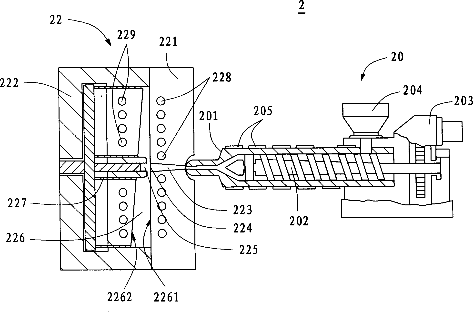
[0018] See figure 2 , Is the first embodiment of the molding device used in the manufacturing method of the light guide plate of the present invention. The molding device 2 includes an injection device 20 and a mold 22. The injection device 20 includes an injection barrel 201, a screw 202 rotatably driven in the barrel 201, a motor 203 that drives the screw 202, a hopper 204 that supplies resin material into the barrel 201, and a hopper 204 provided on the outer surface of the barrel 201 Heater 205. The mold 22 includes a fixed mold 221, a movable mold 222, a channel 225 connecting the two front ends of the fixed mold 221 and the movable mold 222, a flow channel 223 through which molten resin passes and a gate communicating with the flow channel 223 are formed in the fixed mold 221 224. The refrigerant passage 228 of the fixed mold 221 and the refrigerant passage 229 of the movable mold 222. Wherein, the fixed mold 221 and the movable mold 222 form a wedge-shaped mold cavity 226 ...


PUM

PropertyMeasurementUnit
melting pointaaaaaaaaaa

Abstract

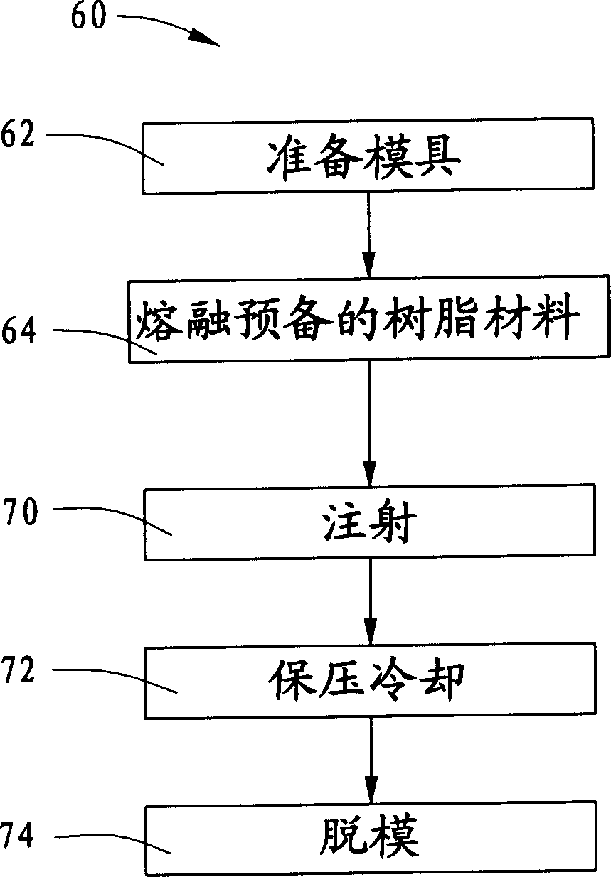
The production process of light guide plate includes the following steps: providing one mold; melting resin material; pouring the molten resin material into cavity of the mold; cooling the mold while maintaining pressure; and demolding to form light guide plate product. The mold has wedged or disc cavity including one plane and one slant or notched surface, and the refrigerant passage for the cooling step is parallel to the plane.

Description

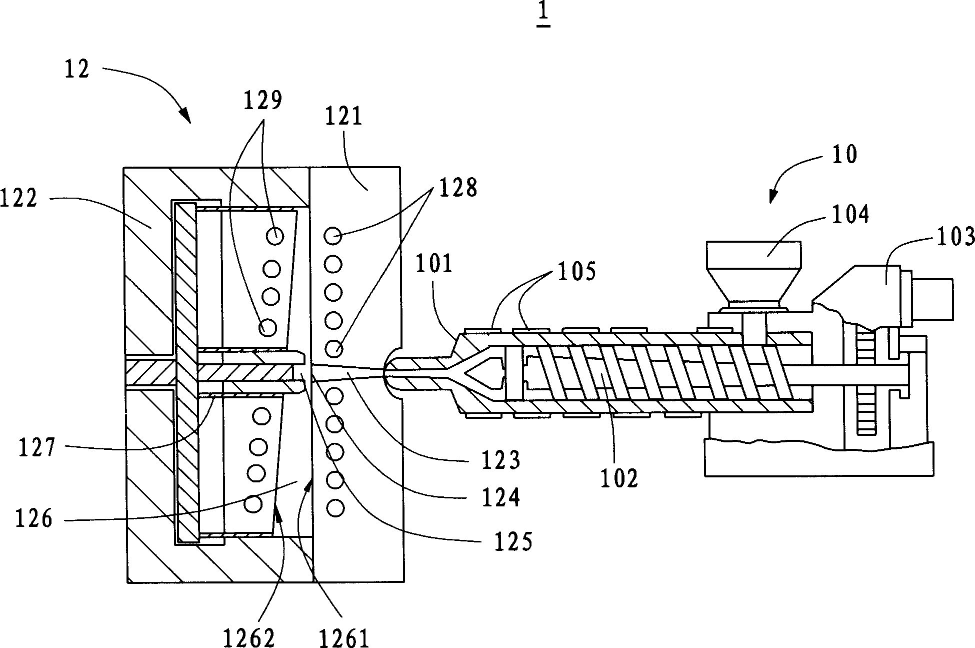
【Technical Field】 [0001] The invention relates to a manufacturing method and a mold for a light guide plate, in particular to a manufacturing method and a mold for a wedge-shaped or dish-shaped light guide plate. 【Background technique】 [0002] The backlight module (Backlight Module) can provide the back light source of electronic products, which is used in various information, communication, and consumer products as the light source system of the liquid crystal display. The working principle of the backlight module is that light directly or indirectly enters the light guide plate and spreads through the bottom surface of the light guide plate with optical structure design and the reflective plate, diffuses and emits at a certain angle, and is evenly distributed in the light-emitting area, and then uses the diffuser and The prism plate adjusts the light viewing angle to meet the optical characteristics of the liquid crystal display. It can be seen that the light guide plate is a ...

Claims


Application Information

Patent Timeline
Patent Type & Authority Applications(China)
IPC IPC(8): B29C45/73
Inventor 陈杰良吕昌岳
Owner HONG FU JIN PRECISION IND (SHENZHEN) CO LTD
Learn More