Information processing method and information processing apparatus
An information processing method and a technology of an information processing device, which are applied in machine execution devices, electrical digital data processing, program control design, etc., and can solve problems such as multiple processes and complicated allocation of storage blocks
- Summary
- Abstract
- Description
- Claims
- Application Information
AI Technical Summary
Problems solved by technology
Method used
Image
Examples
no. 1 Embodiment approach
[0086]
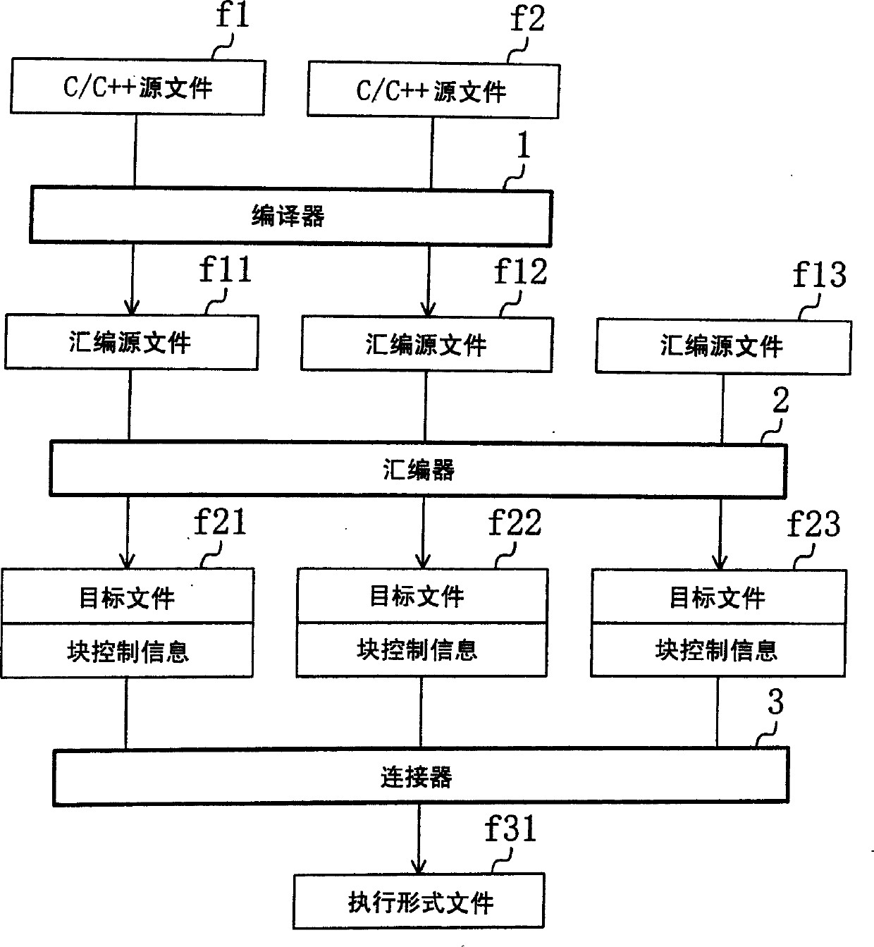
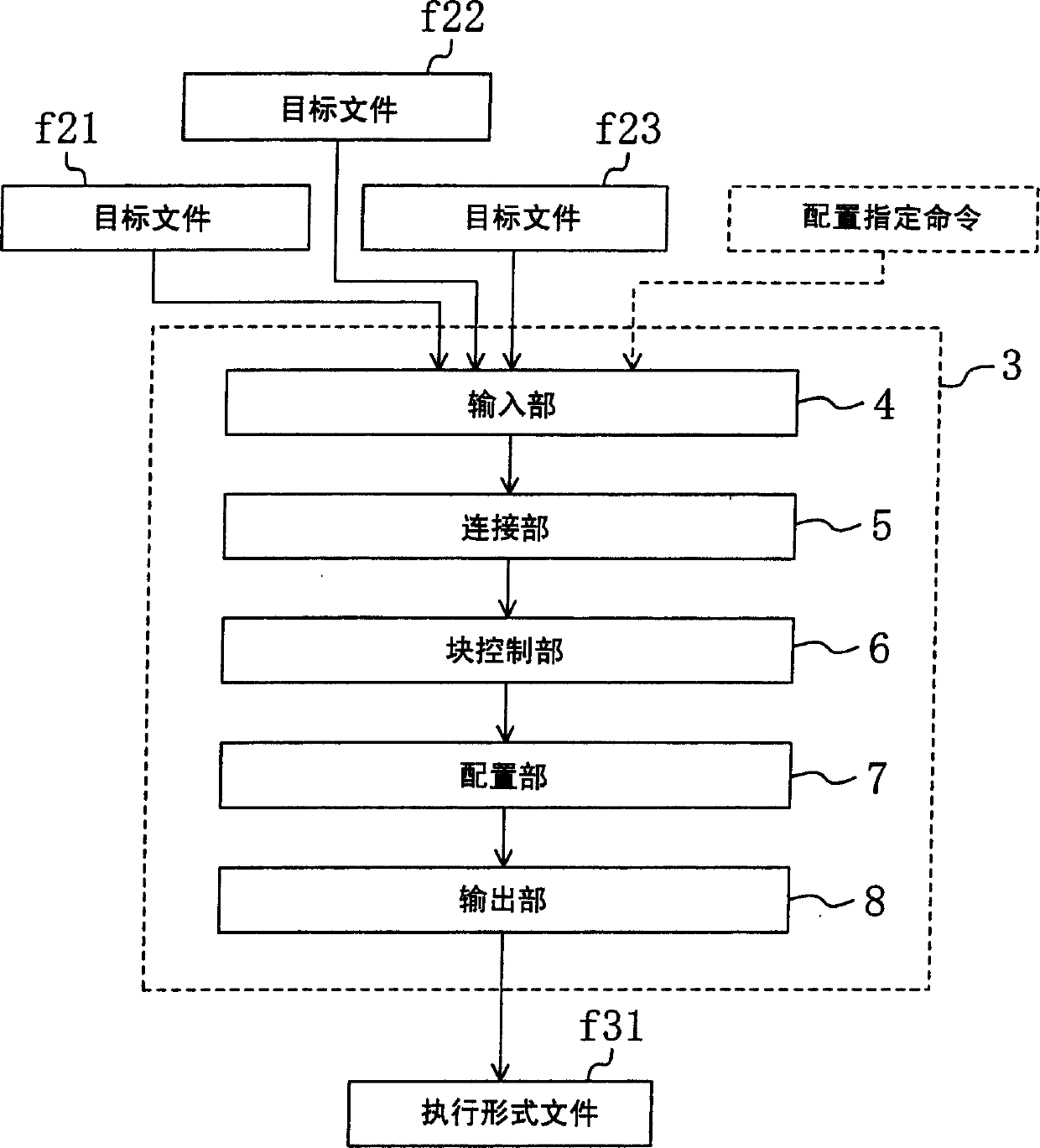
[0087] FIG. 1 shows the configuration of an information processing device according to a first embodiment. This information processing device creates an executable format file f31 based on the C / C++ source files f1 to f2 and the assembler source file f13. C / C++ source files f1-f2 are input files made by users in C / C++ language. The assembly source file f13 is an input file made by the user in assembly language.
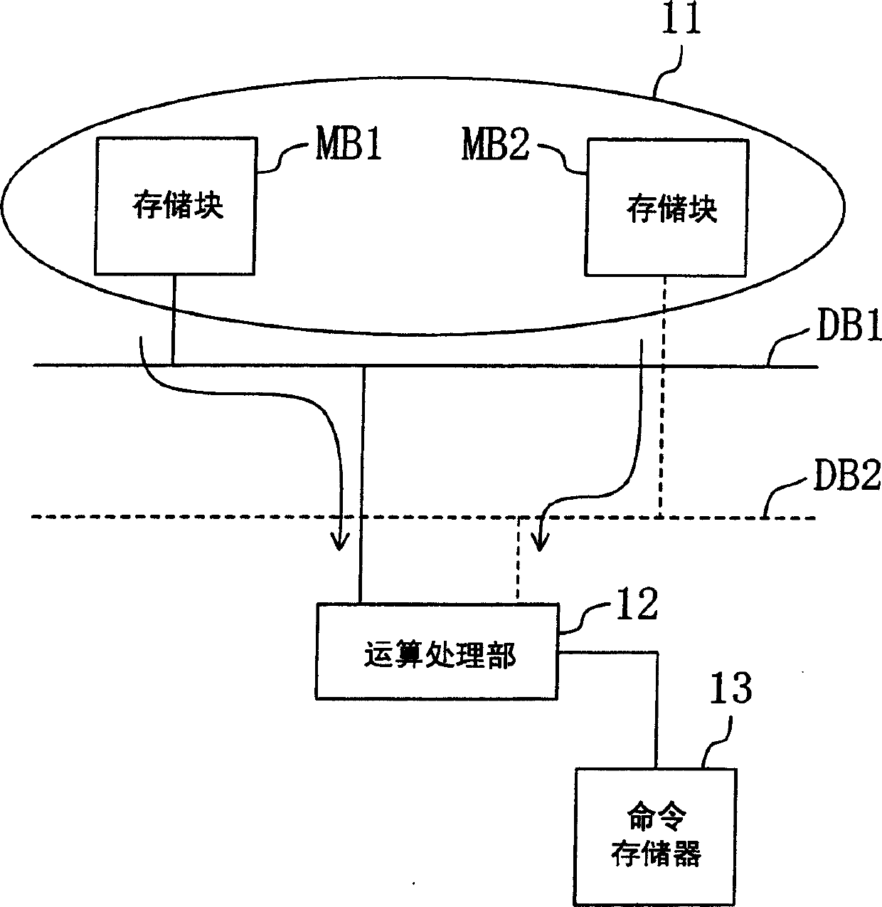
[0088] The execution format file f31 created by this information processing device is executed on the processor (target program computer) shown in FIG. 2 . The processor shown in FIG. 2 includes a data memory 11 , data buses DB1 to DB2 , an arithmetic processing unit 12 , and an instruction memory 13 . The data memory 11 is an area in which data accessed by an operation command is arranged. The data memory 11 includes memory blocks MB1 to MB2. The data bus DB1 is a line connecting the memory block MB1 and the arithmetic processing unit 12 ...
no. 2 Embodiment approach
[0153] In the first embodiment, block allocation is performed on the assumption that the priority of block allocation for all data is equal. In the second embodiment, the block allocation priority is set according to the number of rounds, and block allocation is performed starting from data with a high block allocation priority. In the second embodiment, block control processing shown in FIG. 6 is performed.
[0154] Here, the block control information acquired in the second embodiment will be described using FIG. 47(b). One piece of block control information shown in FIG. 47(b) is created for each read access memory command. The block control information includes a plurality of memory information for storing data, priority information for performing block control, and address information indicating a storage location of the next block control information. Here, the block control priority set in the block control information is assumed to be equal to the number of loops of t...
no. 3 Embodiment approach
[0203] In the fourth embodiment, the block allocation priority is set according to the frequency of use of data, and it is preferable to perform block allocation for data with a high block allocation priority and data used together with data with a high block allocation priority. In the third embodiment, block control processing shown in FIG. 6 is performed. In addition, the block control information acquired in the third embodiment is equivalent to the block control information shown in FIG. 47(b), and the process of acquiring the block control information shown in FIG. 47(b) adopts the method shown in FIG.
[0204] Next, as the block control method in the third embodiment, setting block allocation priority according to the use frequency of data, preferably allocating data with high priority to blocks, and simultaneously with data with high block allocation priority will be described with reference to FIG. 15 . Block control method when using data for block allocation.
[02...
PUM
 Abstract
Description
Claims
Application Information
 - R&D
- Intellectual Property
- Life Sciences
- Materials
- Tech Scout
- Unparalleled Data Quality
- Higher Quality Content
- 60% Fewer Hallucinations
Browse by: Latest US Patents, China's latest patents, Technical Efficacy Thesaurus, Application Domain, Technology Topic, Popular Technical Reports.
© 2025 PatSnap. All rights reserved.Legal|Privacy policy|Modern Slavery Act Transparency Statement|Sitemap|About US| Contact US: help@patsnap.com


