

Friction pad of friction roller for driving bobbin on spinning and weaving machine
A friction pad and friction roller technology, applied in the field of friction pads, can solve the problems of heavy workload and high cost
- Summary
- Abstract
- Description
- Claims
- Application Information
AI Technical Summary
Problems solved by technology
Method used
Image

Examples
Embodiment Construction
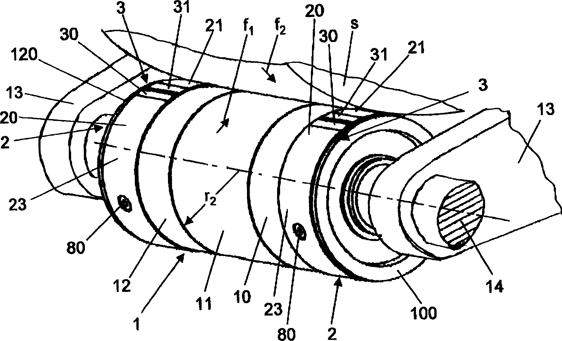
[0026] figure 1 Shown in is a friction roller 1 for driving a package on a textile machine. The friction rollers 1 are driven by a shaft 14 which is rotatably supported in a frame 13 and which extends through several adjacently arranged cartridge positions, each carrying a friction roller 1 .
[0027] The illustrated friction roller 1 consists of three roller bodies 10 , 11 and 12 arranged axially adjacent to one another, the middle roller body 11 being driven by a shaft 14 . The two outer roller bodies 10 and 12 are driven by the middle roller body 11 through a differential transmission, so that the two outer roller bodies 10 and 12 rotate at different speeds. A conical bobbin S placed on the friction roller 1 is driven by two outer roller bodies 10 and 12 . Since the middle roller body 11 does not substantially contribute to the drive of the tapered spool S, only the two outer roller bodies 10 and 12 carry a friction pad 2, while the middle roller body 11 serves essentiall...
PUM
 Abstract
Description
Claims
Application Information