Heat pipe vacuum tube solar energy heat collector

A technology of vacuum tube collectors and glass vacuum tubes, which is applied to solar collectors, solar collectors using working fluids, solar thermal energy, etc., and can solve problems such as performance degradation and thermal performance degradation in summer

Inactive Publication Date: 2004-07-21
孙士明
View PDF0 Cites 4 Cited by
  • Summary
  • Abstract
  • Description
  • Claims
  • Application Information

AI Technical Summary

Problems solved by technology

The solar heat pipe heat collectors installed in these special places either receive less sunlight in winter due to a too small inclination an...

Method used


Image

  • Heat pipe vacuum tube solar energy heat collector
  • Heat pipe vacuum tube solar energy heat collector
  • Heat pipe vacuum tube solar energy heat collector

Examples


Embodiment Construction

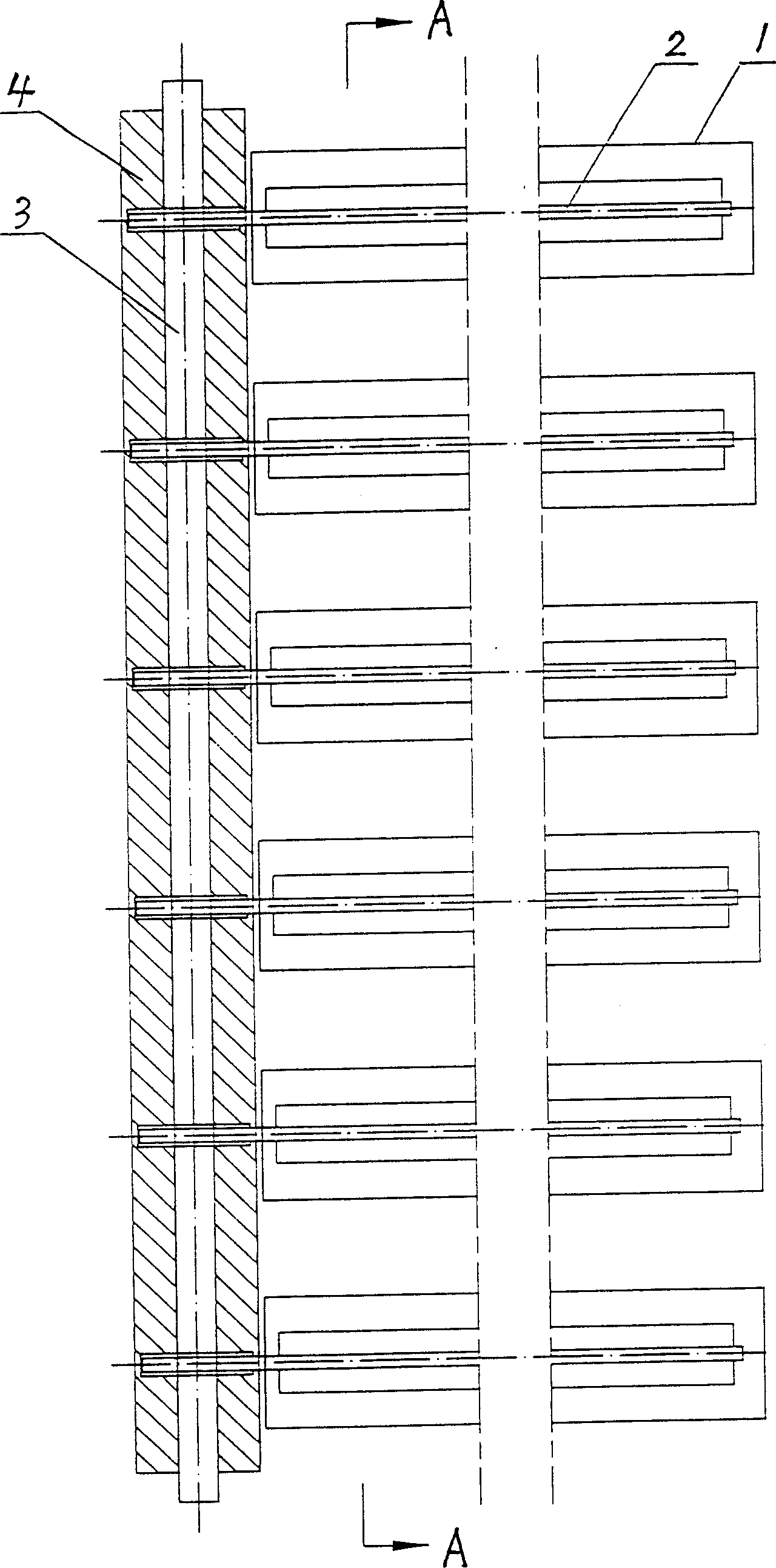
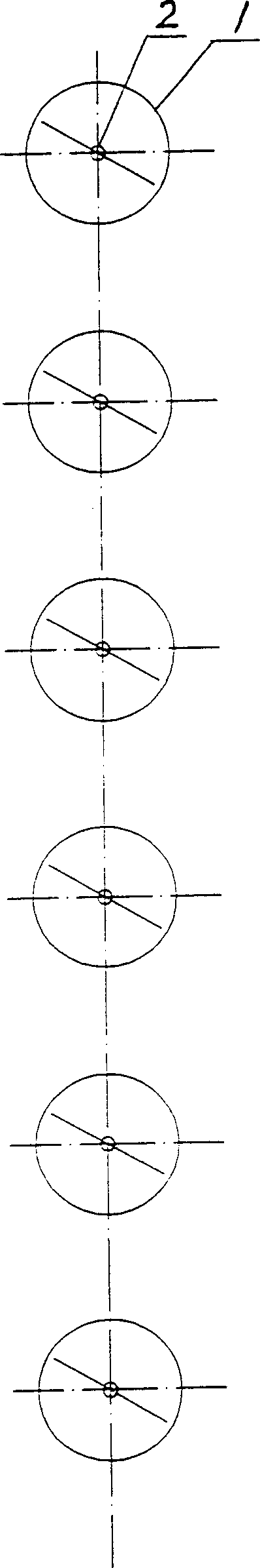
[0016] see first figure 1 and 2 , this figure is a solar heat collector with heat pipe vacuum tubes placed horizontally according to the first embodiment of the present invention.

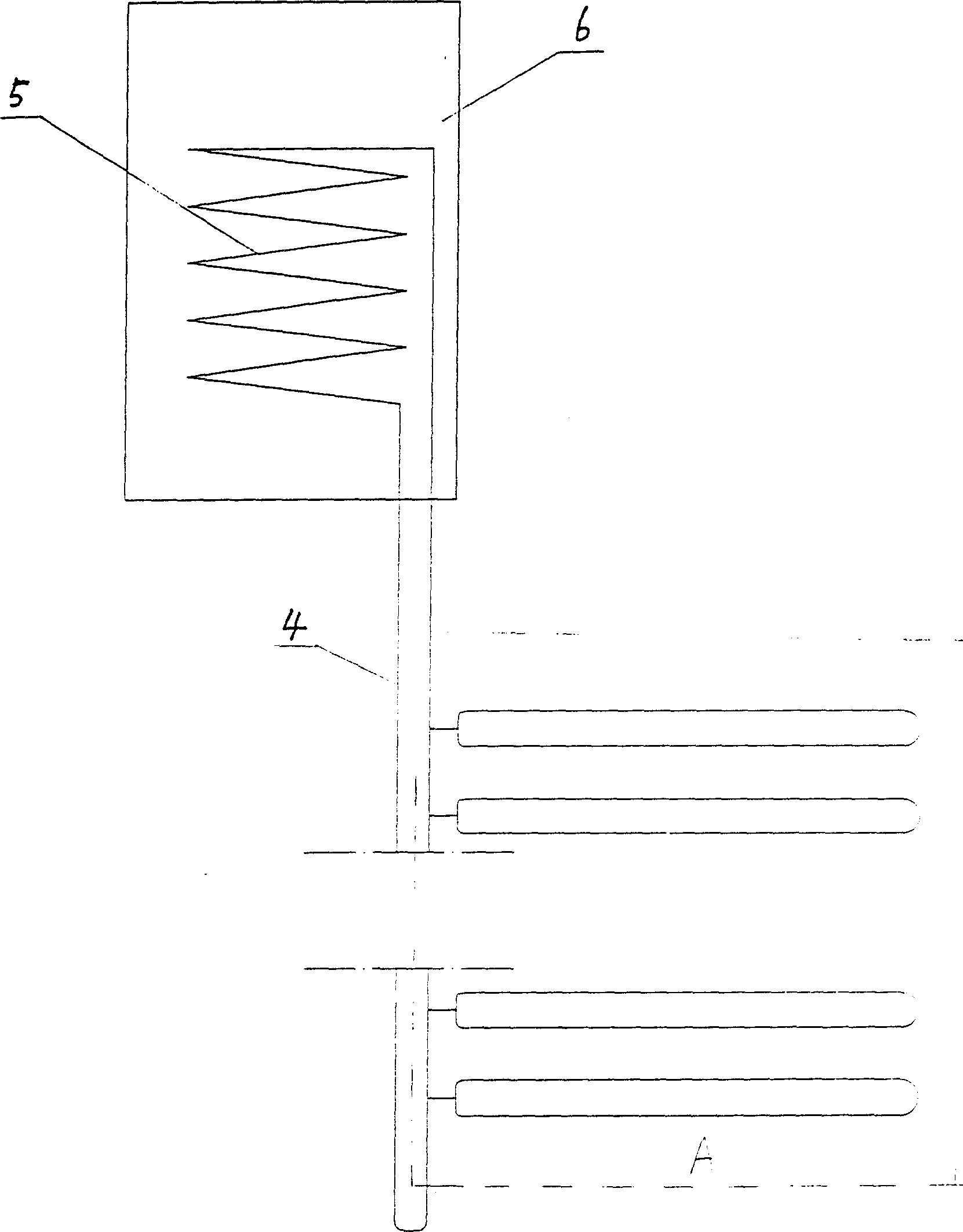
[0017] This embodiment is composed of a glass tube 1 , a gravity heat pipe 2 with ribs, a header 3 and an insulating material 4 .

[0018] The glass tube 1 and the gravity heat pipe 2 inside are placed horizontally, and the fins of the gravity heat pipe 2 can be selected to form an optimal angle with the ground according to the local latitude. The inner diameter of the evaporation section of the gravity heat pipe 2 is greater than 9mm, but considering the linearity of the heat pipe in actual production, the instability of installation and the cost of consumables, the inner diameter is preferably between 12mm and 15mm. The working mass to be filled is greater than 10% of the volume of the evaporating section, but the liquid filling volume should not be too high, otherwise there will be too much li...


PUM

PropertyMeasurementUnit
The inside diameter ofaaaaaaaaaa

Abstract

A heat collector of solar energy is composed of a number of gravity heat pipes, a numbers of glass vacuum pipes and a collector. The gravity heat pipes and glass vacuum pipes are level-placed. The energy received from sunlight can not be influenced when water heater is installed on level surface or on vertical surface.

Description

technical field [0001] The invention relates to a heat pipe vacuum tube solar heat collector. Background technique [0002] The heat pipes currently used in solar heat collectors are all gravity heat pipes and are placed obliquely in use. For sloping roofs with very small inclination angles, balcony railings, etc., it is necessary for the solar collector to be close to the sloping roof or balcony railings for aesthetics. The solar heat pipe heat collectors installed in these special places either receive less sunlight in winter due to a too small inclination angle, resulting in a decrease in performance, or an excessively large inclination angle (90°) causes a substantial decline in summer thermal performance. Contents of the invention [0003] The object of the present invention is to provide a horizontally placed solar gravity heat pipe heat collector which overcomes the above-mentioned drawbacks, and which does not degrade performance in both winter and summer. [000...

Claims


Application Information

Patent Timeline
IPC IPC(8): F24S10/95
CPCY02E10/44
Inventor 孙士明
Owner 孙士明
Why Eureka
Try Eureka