Cutting device for shadow mask support

A cutting device and shadow mask technology, applied in the manufacture of discharge tubes/lamps, discharge tubes, electrical components, etc., can solve problems such as low work efficiency, time-consuming loading and unloading, and increased processing time, and achieve the effect of reducing equipment costs

Inactive Publication Date: 2004-07-28
PANASONIC CORP
View PDF0 Cites 1 Cited by
  • Summary
  • Abstract
  • Description
  • Claims
  • Application Information

AI Technical Summary

Problems solved by technology

Due to such a reaction change, it is difficult to achieve high precision in the degree of cylindricity and curvature of the shadow mask surface.
Moreover, in order to prevent the occurrence of reaction changes, although the frame is precisely positioned by using a three-point support method, it still requires extremely skillful fixing methods, so the productivity is low
[0006] Moreover, in cutting or grinding, if the fixing strength to the frame processing device is reduced in order to prevent the above-mentioned reaction, the processing time will increase due to the necessity of light-load processing.
[0007] In addition, loading and unloading between the frame and the processing device is time-consuming and laborious, and the work efficiency is very low

Method used


Image

  • Cutting device for shadow mask support
  • Cutting device for shadow mask support
  • Cutting device for shadow mask support

Examples


Embodiment Construction

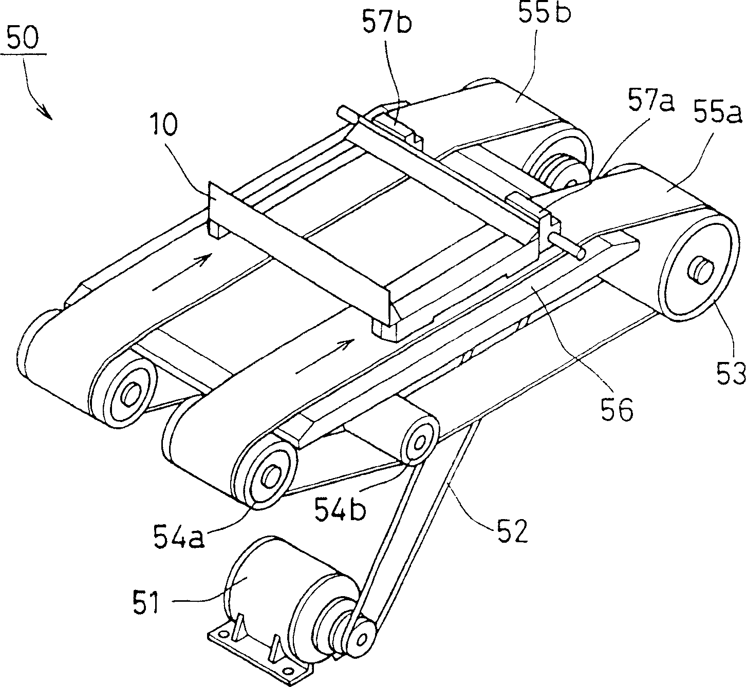
[0024] Below, see Figure 1-Figure 6 Embodiments of the present invention will be described.

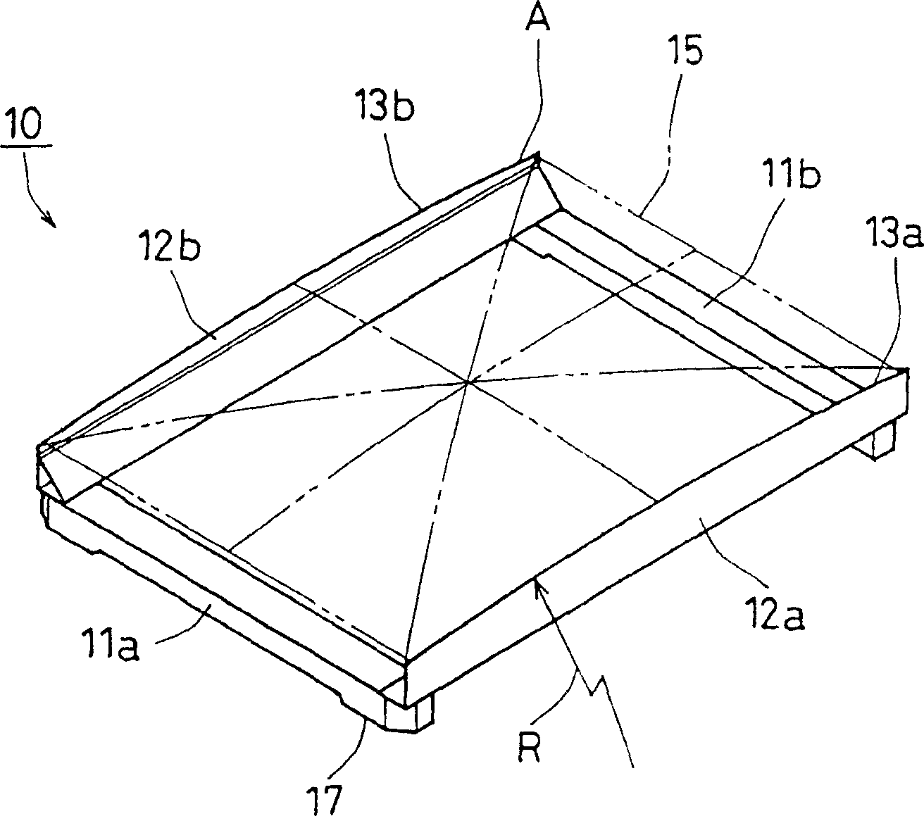
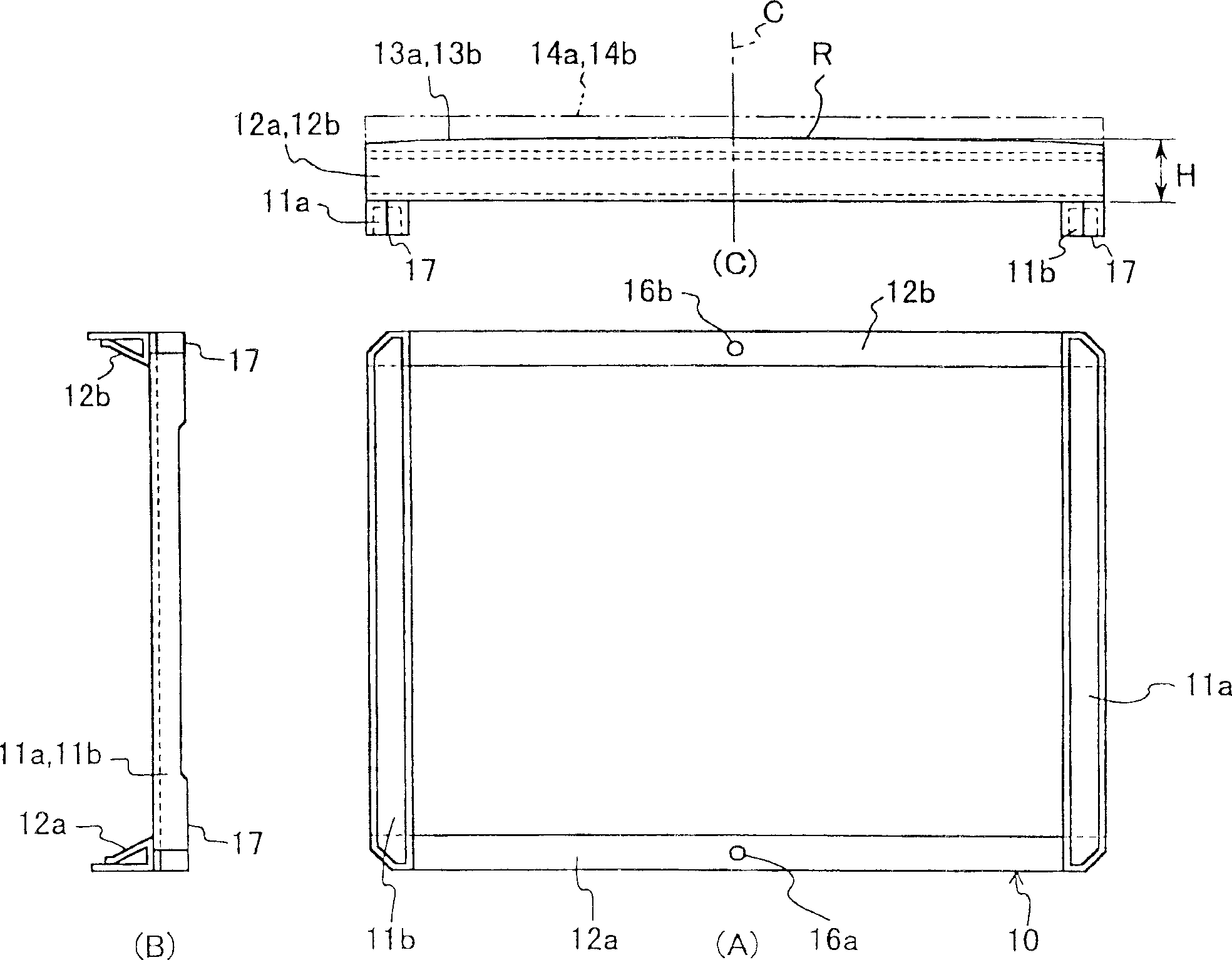
[0025] figure 1 is an oblique sketch showing the structure of the mask frame. while in figure 2 The shadow mask frame structure is also shown, figure 2 (A) is a bottom view, figure 2 (B) is the left side view, figure 2 (C) is a front view.

[0026] As shown in the figure, the shadow mask frame (frame, hereinafter referred to as the frame) 10 is composed of a pair of short side frames 11a, 11b arranged in parallel and a pair of long side frames 12a, 12b arranged in parallel, and the short side frames 11a, 11b and The long side frames 12a, 12b are welded together at the ends. The short side frames 11a and 11b are formed by bending a metal flat plate into a substantially U-shaped cross section. On the other hand, the long side frames 12a, 12b are formed by bending a flat metal plate so that the end faces are substantially triangular. The metal plates forming the long side f...


PUM


Abstract

After assembling a framework 10 in an approximately rectangular form, a basis plane 17 is formed by grinding a bottom surface of the framework. Then, ends of two opposing sides 12a and 12b of the framework on a side opposite to the basis plane are cut in a predetermined shape by shearing. The grinding can be carried out by placing the framework on a grinding surface that is running, while applying substantially no pressurizing force other than the self weight of the framework. According to this method, precision of forming end faces of a framework on which a shadow mask is mounted can be improved. Also, working time can be shortened.

Description

technical field [0001] The present invention relates to a shearing device for a shadow mask frame of a cathode ray tube. In particular, the present invention relates to a device for processing the mounting end surface of a shadow mask, which can be manufactured with extremely high precision when, for example, the ends of the double-sided brackets facing the frame are processed into a curved shape to erect the shadow mask. Cylindricity and curvature of the cylindrical surface formed by the shadow mask surface. Background technique [0002] The shadow mask is generally erected on a frame assembled into a rectangle by means of welding, etc., and installed in the cathode ray tube. The frame is generally configured such that a pair of long side frames are horizontally secured to upper and lower ends of a pair of spaced apart vertically arranged short side frames. Therefore, the shadow mask is mounted on the screen side ends of the pair of long side frames. [0003] The shadow ...

Claims


Application Information

Patent Timeline
Patent Type & Authority Applications(China)
IPC IPC(8): B21D17/00H01J9/14
CPCH01J9/142H01J2229/0722B21D17/00
Inventor 佐藤宪一竹内太造奥村耕之助
Owner PANASONIC CORP
Why Eureka
Try Eureka