Image sensor, and image processing apparatus and information processing system using the same

a technology of image sensor and image processing apparatus, applied in image data processing, instruments, material analysis, etc., can solve problems such as difficult to mold conventional frames b>, shrinkage variations, and unsolved problems, and achieve the effect of higher read resolution

Inactive Publication Date: 2005-11-22
CANON KK +1
View PDF13 Cites 6 Cited by
  • Summary
  • Abstract
  • Description
  • Claims
  • Application Information

AI Technical Summary

Benefits of technology

[0010]The present invention has been made in consideration of the above situation, and has as its object to provide an image sensor...

Problems solved by technology

However, in order to achieve still higher read resolution of the conventional image sensor, the following technical problems remain unsolved.
However, it is hard for conventional molding of the frame 1, which is formed to have an unfilled shape that forms large openings on its outer surface, to obtain a frame thickness that can assure good molding balance with the flatness.
Furthermore, since space L- and M-side blocks, which are partitioned by the space D as the optical path of optical information coming from the document PP, suffer variations in frame thickne...

Method used


Image

  • Image sensor, and image processing apparatus and information processing system using the same
  • Image sensor, and image processing apparatus and information processing system using the same
  • Image sensor, and image processing apparatus and information processing system using the same

Examples


second embodiment

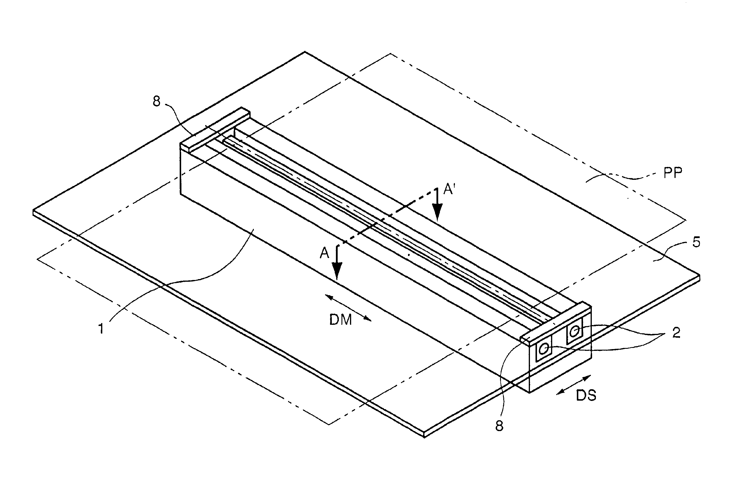
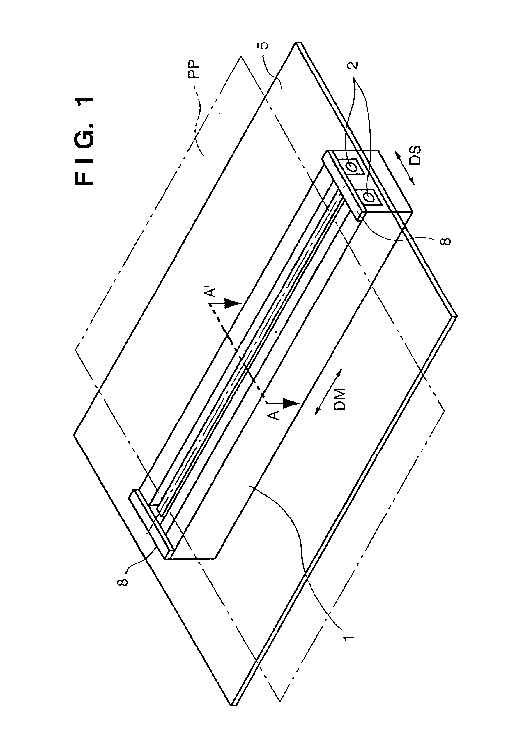
[0051]FIGS. 8 and 9 show the present invention, i.e., a sheet-feeder type image sensor. FIG. 8 is a schematic perspective view showing the outer appearance of the image sensor, and FIG. 9 is a sectional view taken along a line B-B′ in FIG. 8.

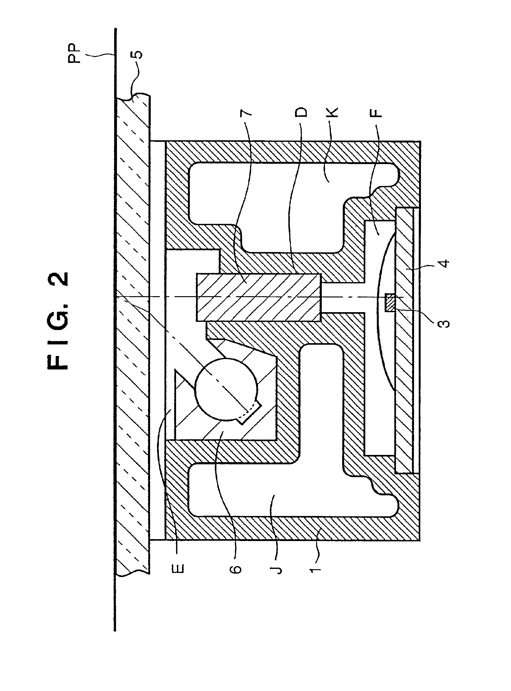
[0052]Referring to FIG. 8, reference numeral 10 denotes a transparent member which is attached to the frame 1 at a position where it can contact a document PP. Reference numeral 9 denotes a roller for conveying the document PP. In FIG. 9, the frame 1 is formed to have hollow spaces J and K.

first embodiment

[0053]With this arrangement, the same effects as in the first embodiment can be obtained for the sheet-feeder type image sensor.

[0054]FIG. 10 shows an example of a facsimile apparatus having a communication function as an image information processing apparatus which uses a sheet-feeder type image sensor unit 100 according to the second embodiment of the present invention. Referring to FIG. 10, reference numeral 102 denotes a feed roller as a feed means for feeding a document PP toward the read position; and 104, a separation piece used to reliably separate and feed documents PP one by one.

[0055]Reference numeral 106 denotes a platen roller as a convey means, which is provided at the read position with respect to the sensor unit to regulate the surface to be read of the document PP and to convey the document PP. Reference symbol P denotes a print medium which is roll paper in FIG. 10. Image information read by the sensor unit or externally received image information in case of the fa...


PUM


Abstract

This invention has as its object to provide an image sensor which can effectively attain higher read resolution, and an image processing apparatus and information processing system using the same. To achieve this object, function members including a light source (6) for irradiating an object to be read (PP) with light, a sensor (3) for receiving light reflected by the object to be read (PP), and an imaging element (7) for forming an image of the reflected light on a light-receiving portion of the sensor (3) are attached to and supported by a support member (1) to have a predetermined positional relationship. In order to assure high attachment positional precision and rigidity for the function members, the support member (1) is formed to have a hollow shape. The support member (1) is formed to have the hollow shape along its longitudinal direction. Two side portions of the support member (1) are formed to have a hollow shape, and are coupled at end portions in the longitudinal direction.

Description

FIELD OF THE INVENTION[0001]The present invention relates to an image sensor for reading light reflected by a document surface to be read (object to be read) using a sensor, and an image processing apparatus and information processing system using the same.BACKGROUND OF THE INVENTION[0002]Conventionally, an image sensor which has a sensor array for performing photoelectric conversion, an imaging element for imaging light coming from a document on the sensor array, and a light source for illuminating the document is known.[0003]FIG. 12 is a schematic perspective view showing the outer appearance of the conventional image sensor. Referring to FIG. 12, reference numeral 1 denotes a frame as a support member; and 5, a top plate glass which can contact a document PP and serves as a transparent member that specifies the read surface. Reference numeral 8 denotes spacers which contact the transparent member 5 to define the position of the sensor with respect to the read position. Most photo...

Claims


Application Information

Patent Timeline
IPC IPC(8): H04N1/03H04N1/031H04N1/028G06T1/00
CPCH04N1/031H04N1/0312H04N1/0315H04N2201/03112H04N2201/0317H04N2201/03129H04N2201/03141H04N2201/03145H04N2201/03179
Inventor NAGATA, KENJI
Owner CANON KK
Why Eureka
Try Eureka