Air-conditioning system

An air-conditioning system and air technology, applied in the direction of air-conditioning systems, ventilation systems, heat recovery systems, etc., can solve problems such as energy loss and energy consumption

Inactive Publication Date: 2004-08-04
LG ELECTRONICS INC
View PDF0 Cites 17 Cited by
  • Summary
  • Abstract
  • Description
  • Claims
  • Application Information

AI Technical Summary

Problems solved by technology

Moreover, since the indoor air is exhausted to the outside during the ventilation process, a large amount of energy is lost. In order to keep the room temperature at the pre-adjusted indoor temperature, more energy needs to be consumed during cooling / heating.

Method used


Image

  • Air-conditioning system
  • Air-conditioning system
  • Air-conditioning system

Examples


Embodiment Construction

[0027] Reference will now be made in detail to the preferred embodiments of the invention and illustrated in the accompanying drawings. In the description of the embodiments, the same components will be given the same names and reference numerals, and overlapping descriptions thereof will be omitted.

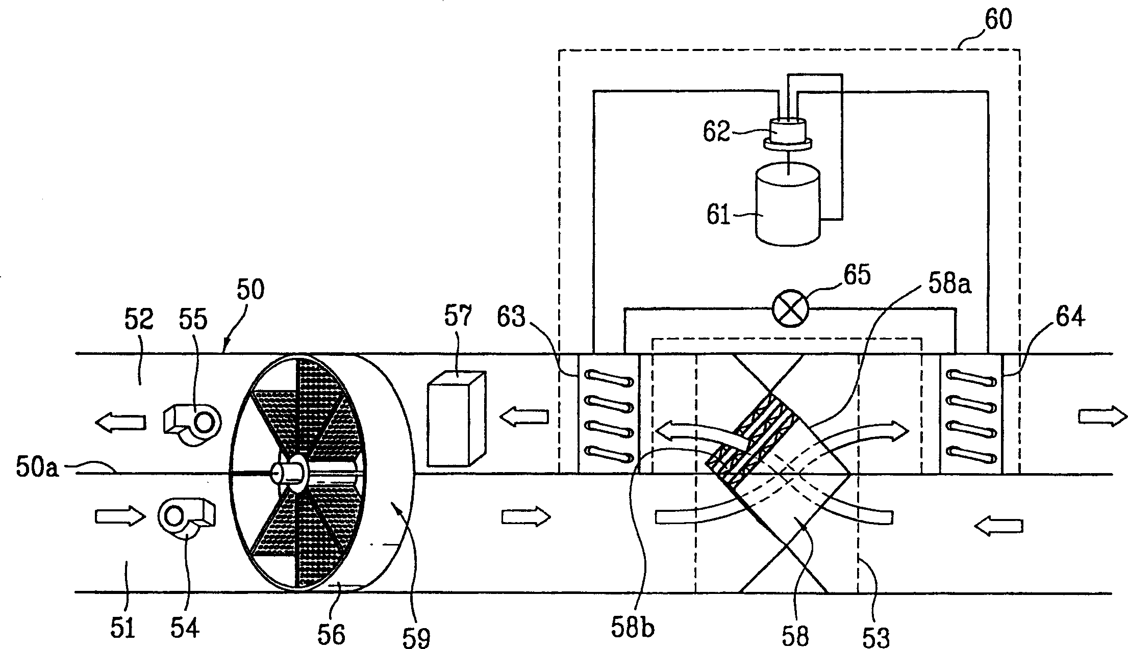
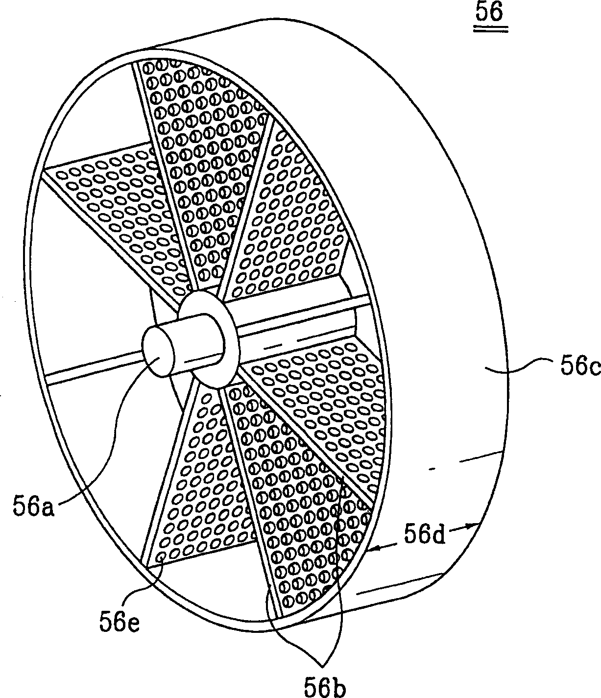
[0028] A first embodiment of the present invention will be described below with reference to the drawings. figure 2 It is the view of the air conditioning system of the first preferred embodiment of the present invention, image 3 for figure 2 Perspective view of a medium dehumidifier drying wheel.

[0029] Such as figure 2 As shown, the air conditioning system of the present invention includes duct 50 , suction fan 54 , exhaust fan 55 , regenerative heat exchanger 58 and heat pump 60 .

[0030] The duct 50 has a suction passage 51 and an exhaust passage 52 separated by a partition plate 50a. The suction fan 54 is installed in the suction channel 51 and is used for sucki...


PUM


Abstract

Air conditioning system including a duct having a suction passage for drawing external air and a discharge passage for discharging room air, the suction passage and the discharge passage being split with a split plate, a suction fan and a discharge fan in the suction passage and the discharge passage, respectively, a dehumidifier having a desiccant wheel rotatably mounted in an opening in a split plate of the duct to cross, and exposed to the suction passage and the discharge passage, a regenerative heater in the discharge passage of the duct adjacent to air inlet of the dehumidifier for heating the air introduced into the dehumidifier, a regenerative heat exchanger mounted both in the suction passage and the discharge passage on a room side with reference to the dehumidifier for making heat exchange of the air flowing in the suction passage and the air flowing in the discharge passage, and a heat pump having a first heat exchanger in the discharge passage between the dehumidifier and the regenerative heat exchanger, and a second heat exchanger in the suction passage on the air outlet of the regenerative heat exchanger.

Description

technical field [0001] The invention relates to an air-conditioning system, in particular to an air-conditioning system with cooling / heating, ventilation and dehumidification functions. Background technique [0002] Generally, air conditioners cool or heat rooms such as residences and offices to provide a comfortable environment. figure 1 A schematic diagram of a cooling / heating system for related art air conditioning. [0003] Such as figure 1 As shown, the refrigeration / heating system of the related art air conditioner is provided with a compressor 1 , a four-way valve 2 , an outdoor heat exchanger 3 , an indoor heat exchanger 4 and an expansion device 5 . There is an outdoor fan 3 a near the outdoor heat exchanger 3 , and an indoor fan 4 a near the indoor heat exchanger 4 . Under the control of the control unit, the cooling / heating system changes the flow direction of the refrigerant flowing through the indoor and outdoor heat exchangers by switching the four-way valve...

Claims


Application Information

Patent Timeline
Patent Type & Authority Applications(China)
IPC IPC(8): F24F3/147F24F3/14F24F7/08F24F12/00F25B13/00
CPCF24F2203/1032F24F12/003Y02B30/52F24F2203/1068Y02B30/16F24F2203/1016F24F2203/108F24F2203/104F25B13/00F24F12/006F24F2203/1084F24F2203/1056Y02B30/563F24F3/1423Y02B30/56F24F3/147
Inventor 李元熙黄允济宋灿豪
Owner LG ELECTRONICS INC
Why Eureka
Try Eureka