Dryness measurement device

A technology for measuring device and dryness, which is applied in washing devices, household clothes dryers, textiles and papermaking, etc., and can solve problems such as inaccurate measurement of dryness

Inactive Publication Date: 2004-08-04
LG ELECTRONICS INC
View PDF0 Cites 4 Cited by
  • Summary
  • Abstract
  • Description
  • Claims
  • Application Information

AI Technical Summary

Problems solved by technology

As a result, the microcomputer 100 cannot accurately measure the dryness because the impedance value at the point of measurement is affected by the outside.

Method used


Image

  • Dryness measurement device
  • Dryness measurement device
  • Dryness measurement device

Examples


Embodiment Construction

[0028] Preferred embodiments of the present invention will now be described in detail with reference to the embodiments shown in the accompanying drawings.

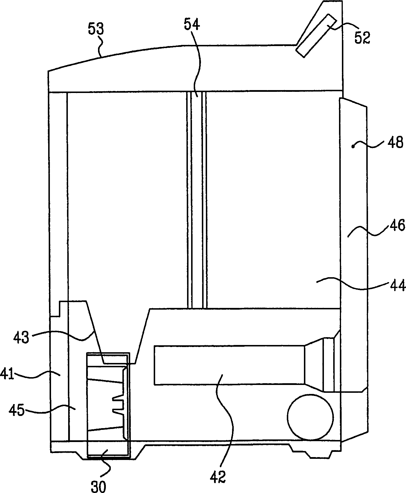
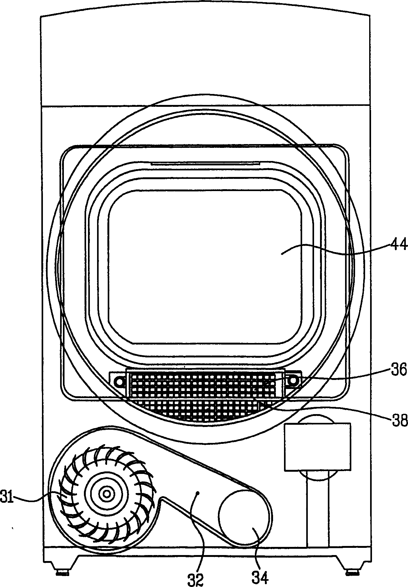
[0029] Figure 5 Shown is the structure of the dryness measuring device in the dryer according to the present invention, wherein the required explanation of the structure of the dryer will refer to FIGS. 1 to 3 .

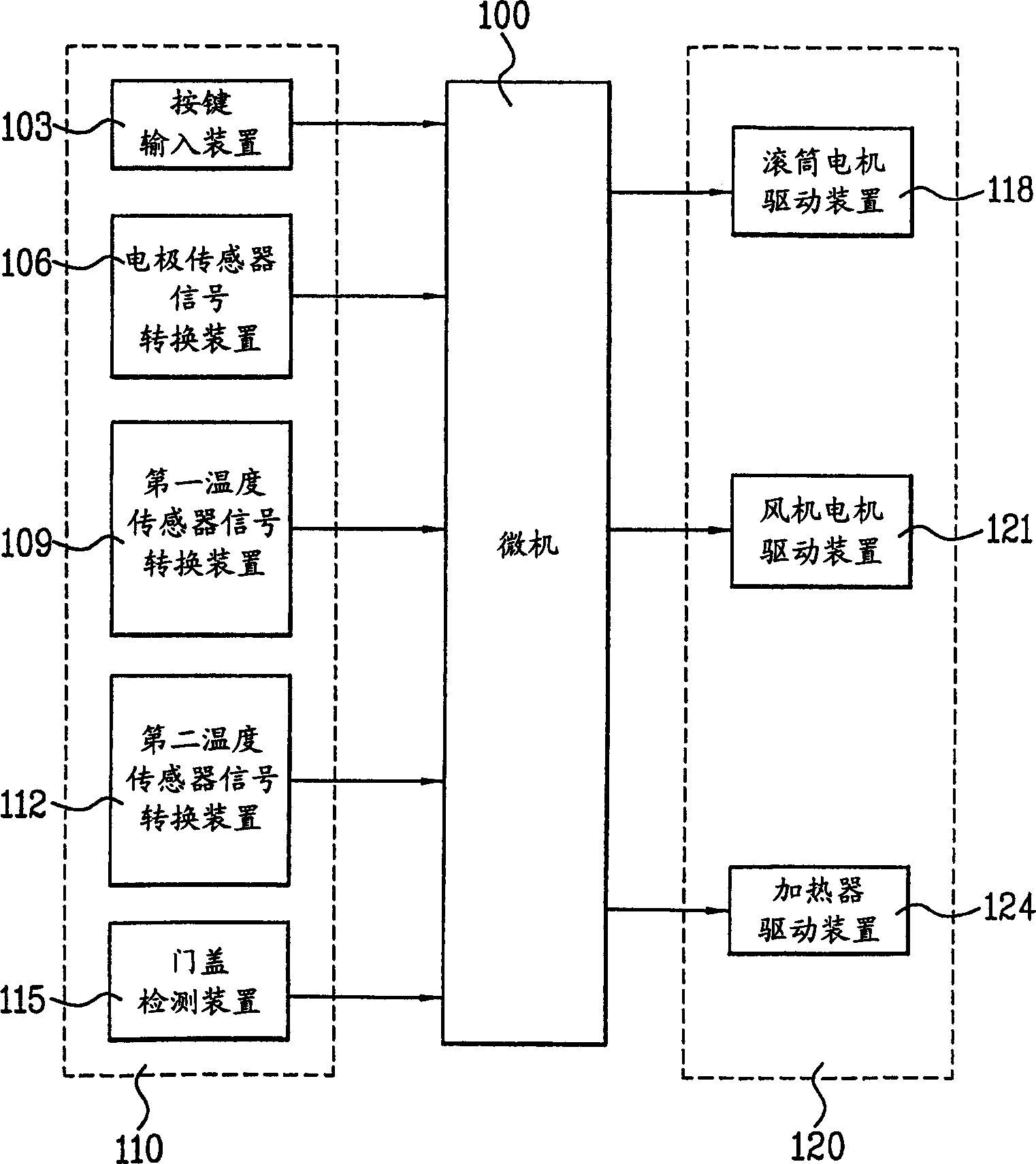
[0030] refer to Figure 5 , in the dryness measuring device of the present invention, the electrode sensor 38 and the capacitor C1 are respectively connected in series with the resistor R1, so that the charging voltage on the capacitor C1 varies with the impedance value of the electrode sensor 38.

[0031] The discharge circuit is provided between the electrode sensor 38 and the capacitor C1.

[0032] The discharge circuit includes a resistor R2 and a transistor Q1 as switching means. When the transistor Q1 is turned on under the control of the microcomputer 100, the charged voltage of the capacitor C1 is rele...


PUM


Abstract

The present invention relates to a dryness measuring device, and more particularly the dryness measuring device for sensing a dryness status of laundry in drying. The present invention is to provide an electrode sensor for sensing the dryness status of the laundry and measuring a current dryness status by a variance of a voltage which is charged in capacitor based on a variance of resistance of the electrode sensor. And, the present invention minimizes outside effect by discharging of the charged voltage of the capacitor by designated periods.

Description

technical field [0001] The invention relates to a drying machine, in particular to a device for measuring the dryness of clothes when the clothes are drying. Background technique [0002] FIG. 1 is a side sectional view of a conventional dryer, and FIG. 2 shows a top view of the conventional dryer. [0003] Referring to Figures 1 and 2, the dryer has a housing 53 forming its outer cylinder. The front panel 41 connected to the front end of the housing 53 forms the front of the dryer. The drum 44 is installed inside the casing 53 and is rotatable, so that clothes can be put into the drum 44 and dried. The drum 44 is rotatable by a drum drive belt 54 wrapped around the outer surface of the drum 44 . [0004] An exhaust hole 43 is provided corresponding to the inner surface of the front plate 41 and opened to the inside of the drum 44 . The function of the exhaust hole 43 is to exhaust the air from the drum 44 . At the inlet of the exhaust hole 43, a lint filter 36 is provi...

Claims


Application Information

Patent Timeline
Patent Type & Authority Applications(China)
IPC IPC(8): G01N27/02D06F58/28
CPCD06F2058/2838D06F58/28D06F34/18D06F58/38D06F2103/10D06F2103/44G01N27/02
Inventor 梁在锡金相斗郑成海
Owner LG ELECTRONICS INC
Why Eureka
Try Eureka