
Tooth hydraulic chain tensioner with rotary reset and locking means

A technology with tensioner and ratchet, which is applied in the direction of transmission, belt/chain/gear, mechanical equipment, etc., and can solve problems such as chain tension fluctuations

Inactive Publication Date: 2004-08-11
BORGWARNER INC
View PDF0 Cites 3 Cited by
  • Summary
  • Abstract
  • Description
  • Claims
  • Application Information

AI Technical Summary

Problems solved by technology

[0003] However, in the harsh environment of internal combustion engines, various factors can cause fluctuations in chain tension

Method used


Image

  • Tooth hydraulic chain tensioner with rotary reset and locking means
  • Tooth hydraulic chain tensioner with rotary reset and locking means
  • Tooth hydraulic chain tensioner with rotary reset and locking means

Examples


Embodiment Construction

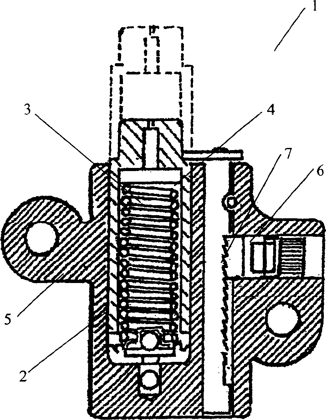
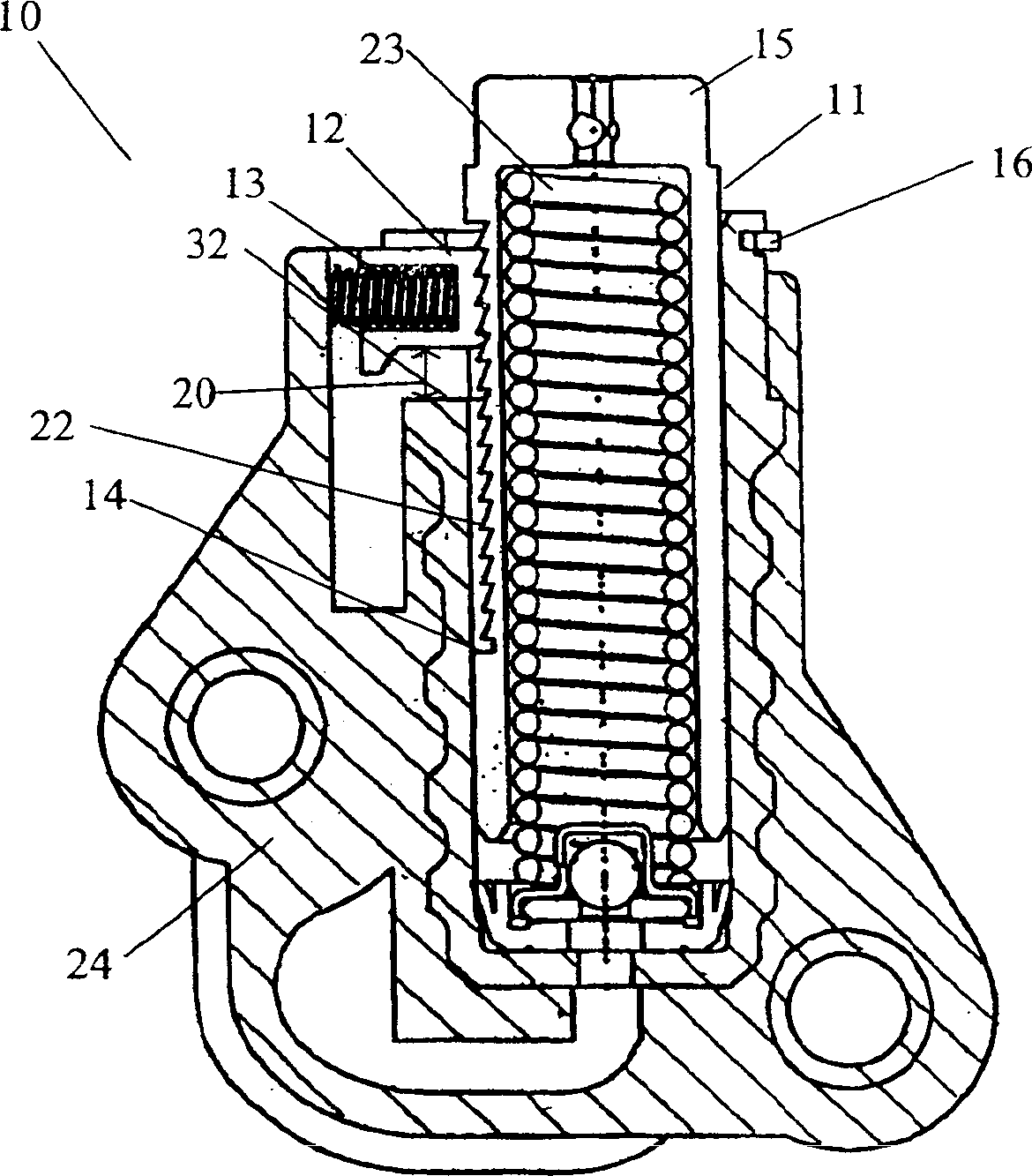
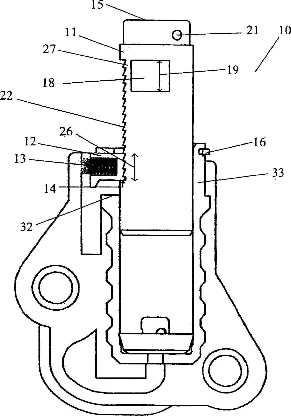
[0017] refer to Figures 2 to 9 , the hydraulic piston tensioner 10 of the present invention has a toothing interface between the piston skirt 11 and the pawl 12 . A tensioner spring 23 biases the piston 15 in the direction of the chain (not shown). The piston is located within the housing 24 .

[0018] The meshing interface between the piston skirt 11 and the pawl 12 includes teeth 22 shaped to allow the piston 15 to extend when the slope of the tooth forces the pawl 12 away from the piston 15 and against the action of its spring 13 . The opposing faces of the teeth 22 prevent piston compression. The teeth 22 are sufficiently recessed into the skirt 11 to provide a shoulder 14 against which the pawl 12 compresses at the predetermined piston position. Even if the teeth are not engaged, the pawl 12 prevents further extension of the piston 15 .

[0019] The pawl 12 is positioned and constrained by the pawl spring 13 , the retaining ring 16 and a series of surfaces formed in ...


PUM


Abstract

A hydraulic chain or belt tensioner (10) includes a ratchet-pawl interface on the piston skirt (11) that can be reset to a locked position by rotating the piston (11) and compressing it until locked. The tensioner preferably includes at least one flat (30) on the piston (11). The flat (30) prevents the piston (11) from rotating axially and locks the piston into place. The locked position is especially useful for shipping the tensioner (10).

Description

technical field [0001] The present invention generally relates to tensioners for use with chain drives in automatic timing and power transmission applications. In particular, the present invention relates to hydraulic chain tensioner systems. Background technique [0002] A tensioning device, such as a hydraulic tensioner, is used as a control device for a power transmission chain or similar power transmission device as the chain moves between multiple sprockets. In this device, the chain transmits power from the drive shaft to the driven shaft so that one part of the chain is slack and the other part is taut. In general, in the case of toothed chains, it is important to impart and maintain a certain degree of tension in the chain to prevent noise, slipping, or misengagement of the teeth. Preventing such slippage is particularly important in the case of a chain driven camshaft in an internal combustion engine, as jumping teeth can break the camshaft timing, potentially cau...

Claims


Application Information

Patent Timeline
Patent Type & Authority Applications(China)
IPC IPC(8): F16H7/08
CPCF16H2007/0878F16H2007/0853F16H2007/0812F16H2007/0806F16H7/0848F16H7/08
Inventor G·L·马克利K·S·肖耶尔
Owner BORGWARNER INC
Learn More