DC brushless motor with decelerator

A brushless DC motor and reducer technology, applied in the direction of DC commutator, electrical components, electromechanical devices, etc., can solve the problems of high speed, difficult maintenance of mechanical brake mechanism, difficult driver design, etc., and achieve the effect of easy disassembly

Active Publication Date: 2004-08-18
SUMITOMO HEAVY IND LTD
View PDF0 Cites 1 Cited by
  • Summary
  • Abstract
  • Description
  • Claims
  • Application Information

AI Technical Summary

Problems solved by technology

[0009] In addition, in the case of using a DC brushless motor for this purpose, the speed will be too high if it is used directly, and it is necessary to attach a reducer in many cases.
[0010] When a mechanical brake mechanism is attached to the drive-integrated DC brushless motor, for example, when the mechanical brake mechanism is attached to the output shaft side of the motor body, the mechanical brake mechanism will be installed between the motor body and the reducer , there will be problems such as difficult maintenance of the mechanical brake mechanism
In addition, if the mechanical brake mechanism is to be installed on the side of the driver opposite to the motor body, it will inevitably form a structure in which the motor shaft of the motor body passes through the center of the driver, which will cause problems such as difficulty in driver design.

Method used


Image

  • DC brushless motor with decelerator
  • DC brushless motor with decelerator

Examples


Embodiment Construction

[0018] Hereinafter, embodiments of the present invention will be described in detail based on the drawings.

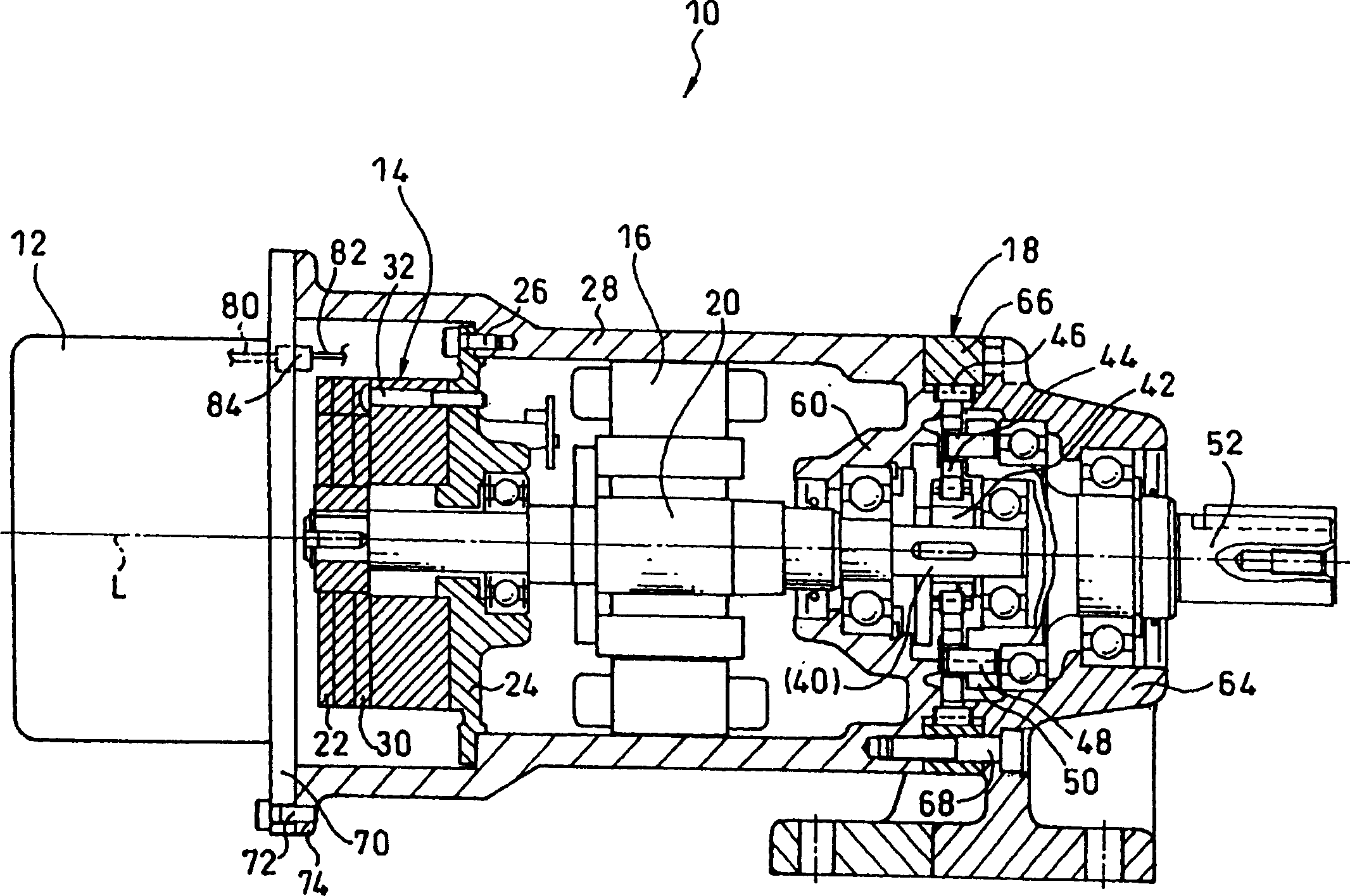
[0019] figure 1 An example of a brushless DC motor with a reducer to which the embodiment of the present invention is applied is shown.

[0020] The DC brushless motor 10 with a reducer includes a driver 12, a mechanical brake mechanism 14 and a motor main body 16 which are sequentially installed on the same axis L. In addition, the reducer 18 is also continuously installed on the same axis L.

[0021] The driver 12 converts single-phase or three-phase alternating current (AC) into direct current (DC), and at the same time generates electrical energy for controlling and driving the motor body 16. The driver 12 has a built-in regenerative braking circuit (the figure is omitted), which is designed to recover the braking energy generated during braking. In addition, the braking of the motor main body 16 that relies on the function of the driver 12 is to reduce the rotation s...


PUM


Abstract

The present invention provides a DC brushless motor with a decelerating machine, which is such a structure for optimally connecting the motor body, driving device, mechanical braking mechanism and decelerating machine of the DC brushless motor. The DC brushless motor 10 with a decelerating machine sequentially comprises: a driving device 12, a mechanical braking mechanism 14, and a motor body 16 on a coaxial wire L, and continuously comprises a decelerating machine 18 on the same coaxial wire L. The driving device lid 70 of the driving device 12 is also used as the lid of the mechanical braking mechanism 14.

Description

Technical field [0001] The invention relates to a DC brushless motor with a reducer. Background technique [0002] Compared with induction motors, brushless DC motors have the advantages of large starting torque and can withstand frequent starts and stops. In addition, it is generally possible to obtain higher accuracy than the structure that uses a so-called inverter to control and drive an induction motor. Therefore, it has been widely used in various fields in recent years. [0003] Brushless DC motors are generally controlled and driven by a controller called a driver. The driver is a pure electrical component. In addition, considering the purpose of concentrating multiple motor main bodies in the factory for driving and control, it is often used A structure in which the driver and the motor body are placed in different positions, and cables are respectively connected to the respective motor bodies. [0004] However, in recent years, due to the production needs of small quant...

Claims


Application Information

Patent Timeline
Patent Type & Authority Applications(China)
IPC IPC(8): H02K29/00H02K7/00H02K7/10H02K7/102H02K7/116H02K11/00H02K23/00
CPCH02K7/102H02K7/116H02K11/30H02K29/00
Inventor 河野功武智哲雄
Owner SUMITOMO HEAVY IND LTD
Why Eureka
Try Eureka