
Super high pressure air-actuated proportional pressure-reducing valve

A proportional pressure reducing valve, ultra-high technology, applied in the direction of fluid pressure actuators, servo motor components, mechanical equipment, etc., can solve the problem of long adjustment time, to avoid pressure errors, improve response speed, and improve pressure control accuracy Effect

Inactive Publication Date: 2004-08-25
ZHEJIANG UNIV
View PDF0 Cites 17 Cited by
  • Summary
  • Abstract
  • Description
  • Claims
  • Application Information

AI Technical Summary

Problems solved by technology

In the field of ultra-high pressure and large flow pneumatic pressure reducing valves, they are all manually controlled. When the output pressure demand changes, it takes a long time to adjust

Method used


Image

  • Super high pressure air-actuated proportional pressure-reducing valve
  • Super high pressure air-actuated proportional pressure-reducing valve

Examples


Embodiment Construction

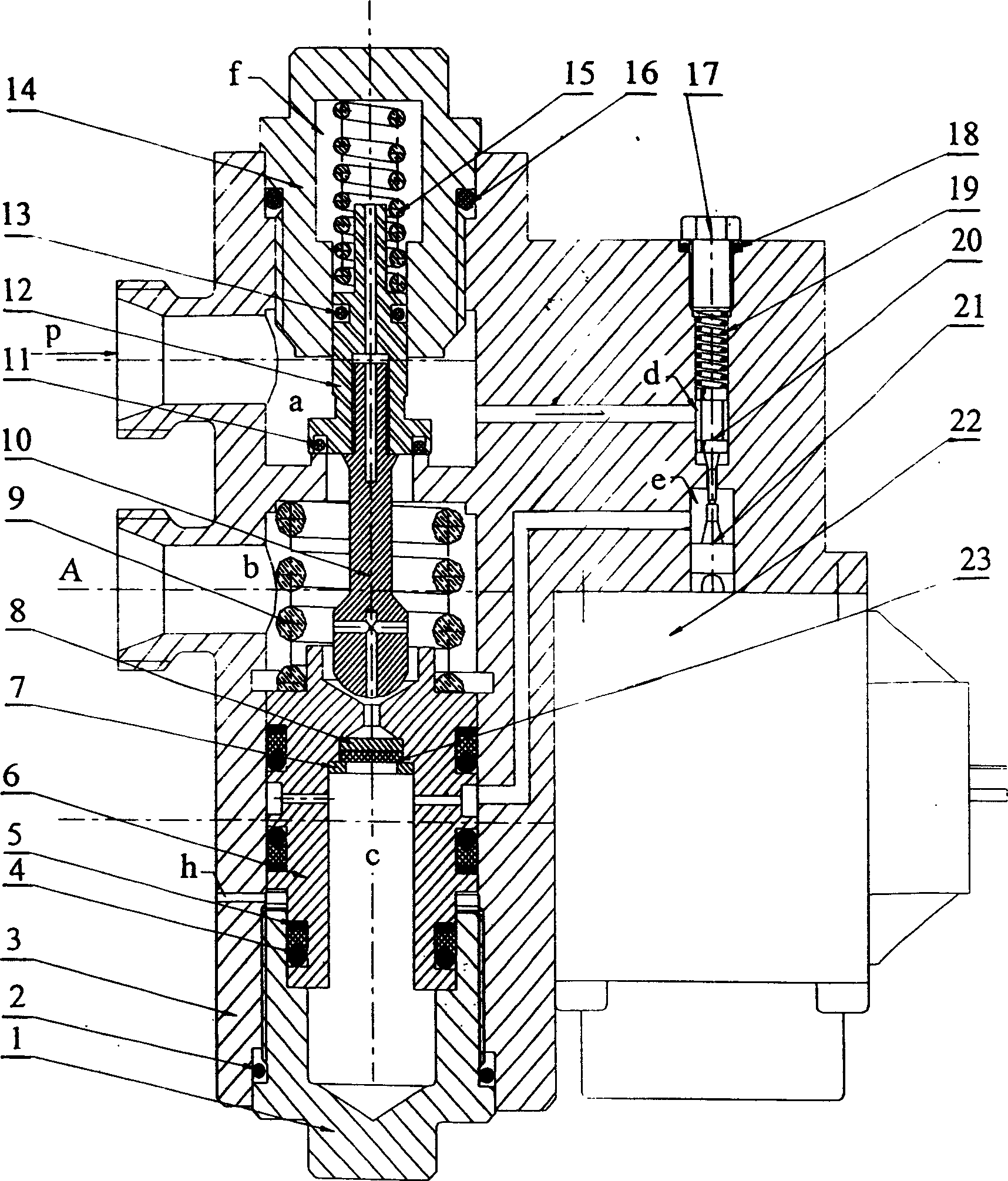
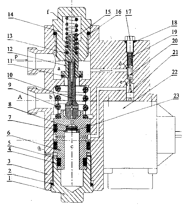
[0018] As shown in the accompanying drawings, the structure of the present invention can be functionally divided into two parts, the pilot valve stage and the main valve stage.

[0019] 1) Pilot stage: the pilot stage gas circuit is a C-type half bridge structure, the input end of the half bridge is led from the input end P of the high-pressure gas of the pressure reducing valve, and the pilot valve controlled by the proportional electromagnet 22 constitutes the dynamic gas damping of the input end, The output end of the half bridge is connected to the output end A of the pressure reducing valve, and the damping plate 23 constitutes the fixed damping of the C-type half bridge; the air inlet chamber d of the pilot stage has a first screw plug 17 and an O-shaped rubber seal from top to bottom. Ring 18, return spring 19, pilot valve spool 20, wherein the O-shaped rubber sealing ring 18 is used for sealing the upper end of the air intake chamber d of the pilot stage. A guide platf...


PUM


Abstract

The present invention discloses an extra high pressure pneumatic proportional reducing valve, and it is characterized by that it adopts proportional pilot valve and electric feedback technique to implement full automatic pressure control, save human resources and raise reaction speed. Its main valve adopts gas pressure control, regulated pressure is high, the designed maximum input pressure can be up to 40 MPa, and output pressure is 0-25 MPa, and said pressure can be continuously regulated. Its pilot-level gas circuit adopts C-type semibridge structure, the pilot valve controlled by proportional electromagnetic iron is formed into the dynamic damping of input end, the damping plate can be used as fixed damping of output end. The input end of pilot valve is led from air inlet end of reducing value, and its output end is connected with air outlet end of the reducing valve. After the system is powered off, the pilot valve and main valve can be automatically closed by action of reset spring and gas pressure.

Description

Technical field [0001] The invention relates to a pressure reducing valve, in particular to an ultra-high pressure pneumatic proportional pressure reducing valve. Background technique [0002] Ultra-high pressure pneumatic pressure reducing valves. At present, most domestic pneumatic pressure reducing valves are manual pressure reducing valves with a low degree of automation. The output pressure of the pressure reducing valve is usually below 10Mpa. In the field of ultra-high pressure and large flow pneumatic pressure reducing valves, they are all manually controlled. When the output pressure demand changes, it takes a long time to adjust. Contents of the invention [0003] The purpose of the present invention is to provide an ultra-high pressure pneumatic proportional pressure reducing valve with a relatively simple structure, which has good controllability of the outlet pressure and a wide range of pressure regulation. It is continuously adjustable and has a large appl...

Claims


Application Information

Patent Timeline
Patent Type & Authority Applications(China)
IPC IPC(8): F15B13/044
Inventor 王宣银陈奕泽程佳梁冬泰
Owner ZHEJIANG UNIV
Learn More