Multiplexing apparatus

A technology for light devices and light concentrators, applied in lighting devices, light guides, optics, etc., can solve the problems of light leakage, difficult positioning, affecting light coupling efficiency, etc., and achieve the effect of reducing manufacturing costs

Inactive Publication Date: 2004-08-25
DELTA ELECTRONICS INC
View PDF0 Cites 4 Cited by
  • Summary
  • Abstract
  • Description
  • Claims
  • Application Information

AI Technical Summary

Problems solved by technology

[0005] However, the high heat generated by the high-power light source 108 easily deteriorates the glue maintaining the gap, making it difficult to accurately maintain the positioning between the prism 102 and the light pipe 104; 104A will cause part of the light to leak out throug

Method used


Image

  • Multiplexing apparatus
  • Multiplexing apparatus
  • Multiplexing apparatus

Examples


Embodiment Construction

[0042] Embodiments of the present invention will be described in detail below with reference to the accompanying drawings.

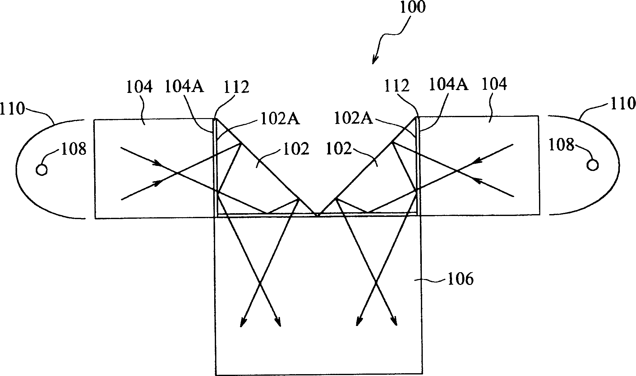
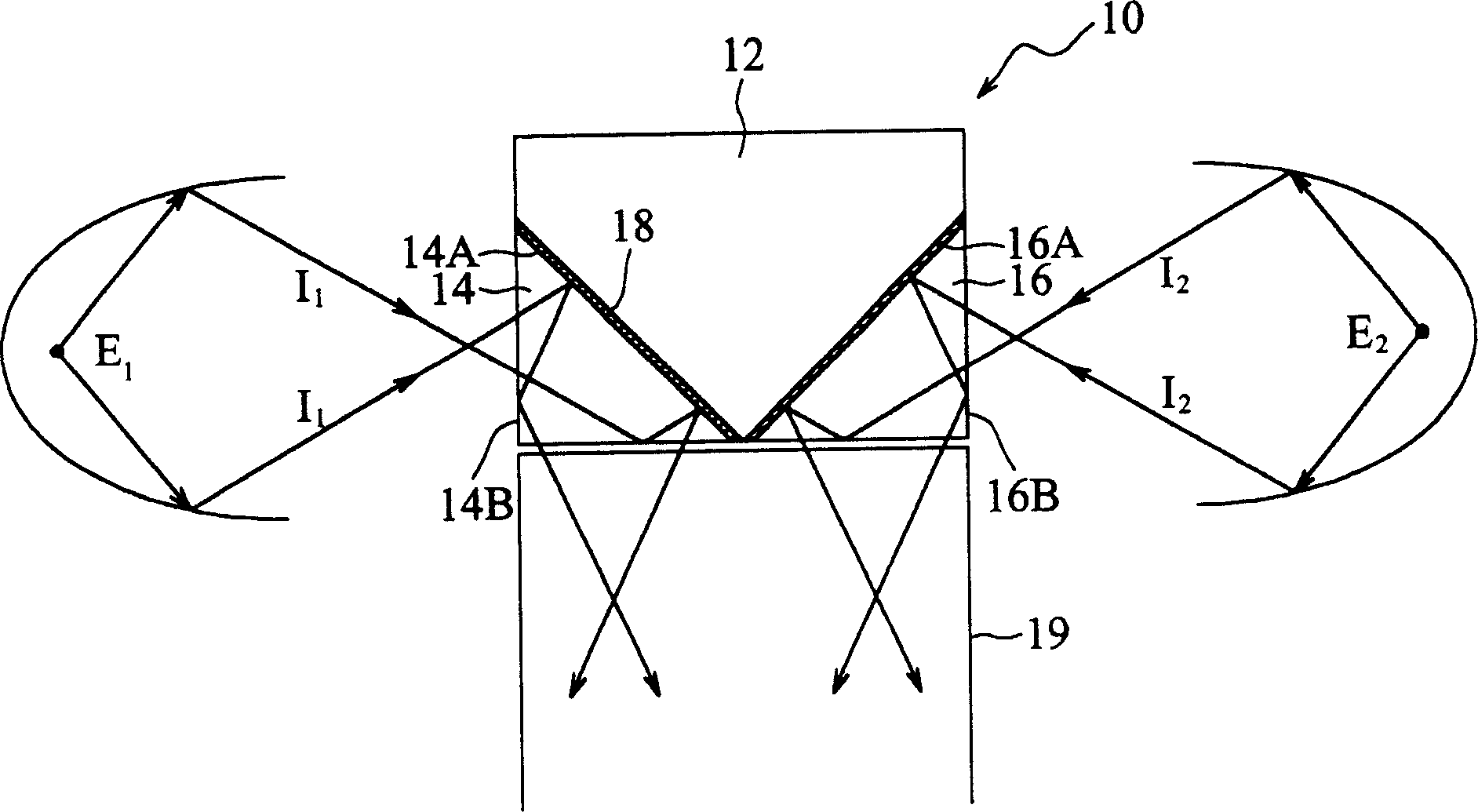
[0043] figure 2 It is a schematic diagram showing a preferred embodiment of the light combining device 10 of the present invention. Such as figure 2 As shown, the light combination device 10 includes a heat dissipation block 12 , a prism 14 and a prism 16 .

[0044] In this embodiment, the prisms 14 and 16 are preferably rectangular prisms, and each surface of the prisms is polished to form a smooth surface. Such as figure 2 As shown, one inclined surface of the prism 14 and the prism 16 is also coated with a high reflectivity coating (High reflection coating) 18 to form the reflective surfaces 14A and 16A. The heat dissipation block 12 can be made of a material with high heat conduction efficiency, such as metal material such as copper. The prism 14 and the prism 16 are respectively attached to the heat dissipation block 12 with the reflective s...


PUM


Abstract

The invention is an optical combining device, including a cooling component and many prisms. Each prism has a reflector coated with a high-reflection coating, and jointed on the cooling component through the reflector.

Description

technical field [0001] The invention relates to a light combination device, in particular to a light combination device which is easy to be positioned precisely during assembly and has high heat dissipation efficiency. Background technique [0002] figure 1 It is a schematic diagram showing a conventional light combining device 100 . Such as figure 1 As shown, the light combination device 100 is composed of a prism 102 , a light guide 104 , a light guide 106 , a light source 108 and a reflector 110 . When the light emitted by the light source 108 on both sides is directly or reflected by the reflector 110, it enters the light guide 104 and is then introduced into the prism 102. Since the light will be reflected by different mirror surfaces in the prism 102, it will be output through the light guide 106. , therefore, the combined light effect of combining light from different light sources to output in the same output direction is obtained. [0003] To obtain the above-me...

Claims


Application Information

Patent Timeline
IPC IPC(8): F21V3/00G02B5/04G02B6/00G02B27/10
Inventor 张绍雄
Owner DELTA ELECTRONICS INC
Why Eureka
Try Eureka