Image display device equipment with checking terminal
A technology of an image display device and an image display panel, which is applied in the directions of measuring devices, identification devices, static indicators, etc., to achieve the effects of accurate inspection and cost reduction
- Summary
- Abstract
- Description
- Claims
- Application Information
AI Technical Summary
Problems solved by technology
Method used
Image

Examples
Embodiment 1
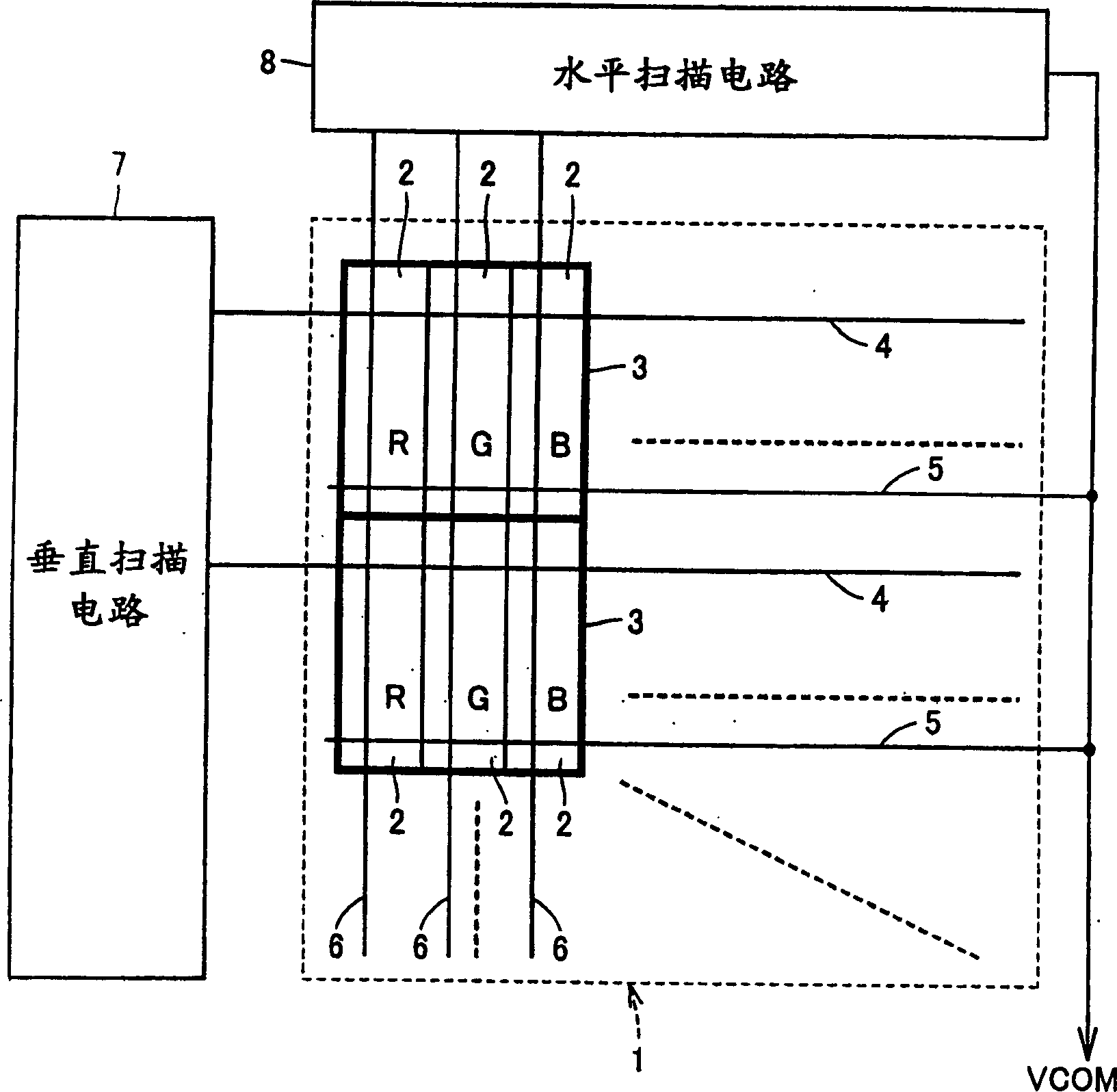
[0021] figure 1 It is a block diagram showing the configuration of the color liquid crystal display device according to Embodiment 1 of the present invention. Such as figure 1 As shown, the color liquid crystal display device is provided with: a liquid crystal panel 1, a vertical scanning circuit 7 and a horizontal scanning circuit 8, and the device can be set on a mobile phone, for example.
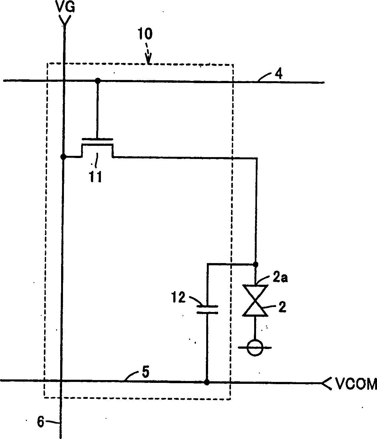
[0022] The liquid crystal panel 1 includes: a plurality of liquid crystal cells 2 arranged in a plurality of rows and a plurality of columns, a plurality of scanning lines 4 respectively corresponding to a plurality of rows, a plurality of common potential lines 5 respectively corresponding to a plurality of rows and corresponding A plurality of data lines 6 arranged in a plurality of columns. A plurality of common potential lines 5 are connected to each other.
[0023] The liquid crystal cells 2 form a group of three in each row in advance. The three liquid crystal cells 2 in each g...
Embodiment 2
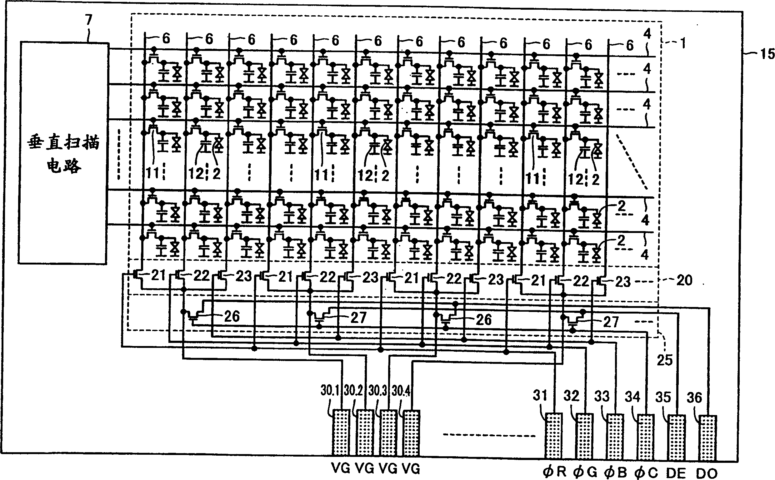
[0046] Figure 7 is a diagram illustrating an inspection method of an LCD module according to Embodiment 2 of the present invention. exist Figure 7 In this inspection method, a plurality of (three in the figure) LCD modules 41 to 43 are formed on the surface of a glass substrate 40 . Each LCD module 41-43 and image 3 same as shown in . The terminals 31 to 36 used for inspection of the respective LCD modules 41 to 43 are arranged facing one side of the glass substrate 40 . Further, along this side of the glass substrate 40 , an R terminal 51 , a G terminal 52 , a B terminal 53 , control terminals 54 to 56 , an even data terminal 57 , and an odd data terminal 58 are arranged.
[0047] The R terminals 31 of the LCD modules 41 to 43 are all connected to the R terminal 51 . The G terminals 32 of the LCD modules 41 to 43 are all connected to the G terminal 52 . The B terminals 33 of the LCD modules 41 to 43 are all connected to the B terminal 53 . The control terminals 34 o...
Embodiment 3
[0052] FIG. 8 is a diagram illustrating an inspection method of an LCD module according to Embodiment 3 of the present invention. In this inspection method of FIG. 8 , a plurality of (three in the figure) LCD modules 61 to 63 are formed on the surface of a glass substrate 60 . The external terminal portions 61 a to 61 c of the LCD modules 61 to 63 are disposed facing one side of the glass substrate 60 . Along the external terminal portions 61a-61c of the LCD modules 61-63, terminal switching circuits 64-66 for inspection are provided, respectively. Further, along this side of the glass substrate 60 , an R terminal 71 , a G terminal 72 , a B terminal 73 , control terminals 74 to 76 , an even data terminal 77 , and an odd data terminal 78 are provided.
[0053] Figure 9 is a circuit block diagram showing the structure of the LCD module 61 for use with image 3 comparing. refer to Figure 9 , LCD module 61 with image 3 The LCD module differs in that the inspection termina...
PUM
 Abstract
Description
Claims
Application Information
 - R&D
- Intellectual Property
- Life Sciences
- Materials
- Tech Scout
- Unparalleled Data Quality
- Higher Quality Content
- 60% Fewer Hallucinations
Browse by: Latest US Patents, China's latest patents, Technical Efficacy Thesaurus, Application Domain, Technology Topic, Popular Technical Reports.
© 2025 PatSnap. All rights reserved.Legal|Privacy policy|Modern Slavery Act Transparency Statement|Sitemap|About US| Contact US: help@patsnap.com