Thin-wall mould casing member

A formwork component and thin-walled technology, which is applied to building components, building structures, floors, etc., can solve problems such as unreasonable mechanical performance, increasing the cross-sectional size of dense ribs, increasing the cost of floors, etc.

Inactive Publication Date: 2004-09-22
邱则功
View PDF3 Cites 2 Cited by
  • Summary
  • Abstract
  • Description
  • Claims
  • Application Information

AI Technical Summary

Problems solved by technology

However, after being applied to dense ribbed floors, the formed dense ribs are all rectangular dense ribs, and their mechanical performance is not very reasonable. It is often necessary to increase the cross-sectional size of the dense ribs, increase the amount of steel bars and concrete, and increase the cost of the floor. , therefore, it is urgently needed to develop a new type of thin-walled formwork member

Method used


Image

  • Thin-wall mould casing member
  • Thin-wall mould casing member
  • Thin-wall mould casing member

Examples


Embodiment Construction

[0060] The present invention will be further described below with reference to the accompanying drawings and embodiments.

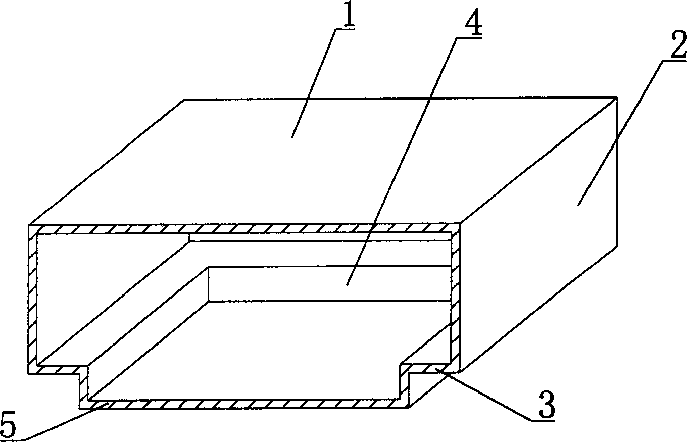
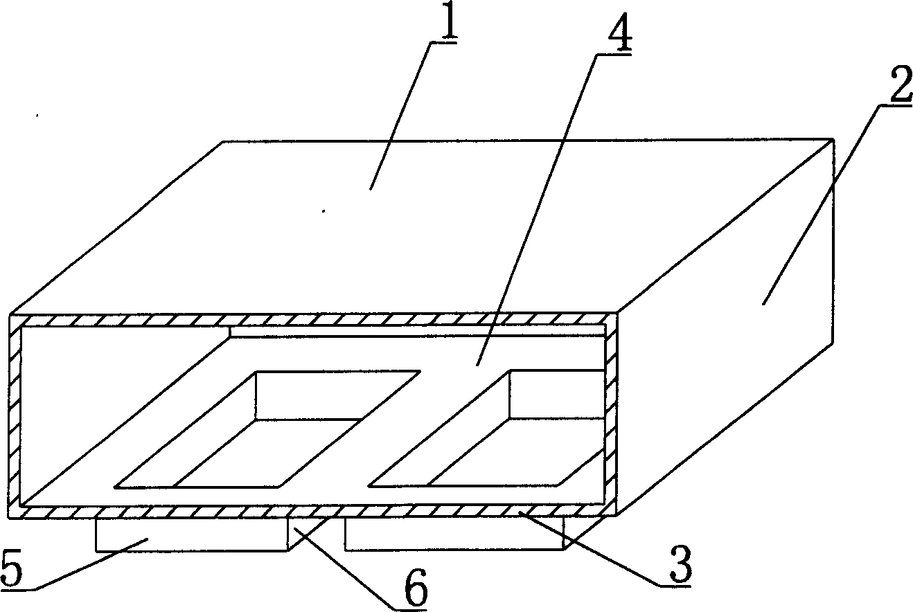
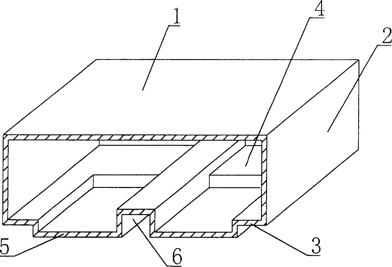
[0061] As shown in the accompanying drawings, the present invention includes an upper plate 1, a peripheral side wall 2, and a lower bottom 3, and the upper plate 1, the peripheral side wall 2, and the lower bottom 3 enclose a polyhedral cavity 4. It is characterized in that the lower bottom 3 has at least A boss module 5 protruding from the lower base 3 . figure 1 It is a schematic structural diagram of Embodiment 1 of the present invention. In the accompanying drawings, 1 is the upper plate, 2 is the surrounding side wall, 3 is the lower bottom, 4 is the polyhedral cavity surrounded by the upper plate, the surrounding side wall and the lower bottom, 5 is the boss module, in each drawing, the number The same, the description is the same. like figure 1 As shown, the lower base 3 has a boss module 5 protruding from the lower base 3 .

[0062] The prese...


PUM


Abstract

A thin-wall moulded shell member for floor is composed of top plate, 4 side walls and bottom plate with at least one convex part, all of which are combined to surround an empty cavity. When it is used for the dense-rib floor, its cross-section is changed from rectangular shape to reverse T-letter shape, so greatly improving its mechanical performance. Its advantages are less consumption of reinforcing bars and concrete, high strength, and low cost.

Description

(1) Technical field [0001] The present invention relates to a thin-walled formwork member. (2) Background technology [0002] At present, the cast-in-place concrete hollow floor is a widely used floor structure. The lightweight permanent mold filled in it includes various hollow tubes and boxes, and the boxes are hollow or solid. For example, the patent number ZL99249798.1 filed by the applicant on November 29, 1999 and the utility model patent titled "Fiber-reinforced thin-walled member for reinforced concrete filling" discloses a thin-walled formwork member, including an upper plate, The surrounding side wall, the lower bottom, the upper plate, the surrounding side wall and the lower bottom form a polyhedral cavity. Another example is the utility model patent applied by Liang Jun of Shijiazhuang City, Hebei Province on February 23, 2000, the patent number is ZL00203695.9 and the name is "combined concrete concealed rib floor cover plate". It can be solid or hollow, and i...

Claims


Application Information

Patent Timeline
Patent Type & Authority Applications(China)
IPC IPC(8): E04B5/36
Inventor 邱则功
Owner 邱则功
Why Eureka
Try Eureka