Silencer with variable damp characteristics

A technology of damping characteristics and mufflers, which is applied in the direction of mufflers, machines/engines, mechanical equipment, etc., and can solve problems that have not been adopted

Inactive Publication Date: 2004-09-22
HEINRICH GILLET GMBH & CO KG
View PDF3 Cites 11 Cited by
  • Summary
  • Abstract
  • Description
  • Claims
  • Application Information

AI Technical Summary

Problems solved by technology

Therefore, none of the above designs have been adopted in practice.

Method used


Image

  • Silencer with variable damp characteristics
  • Silencer with variable damp characteristics
  • Silencer with variable damp characteristics

Examples


Embodiment Construction

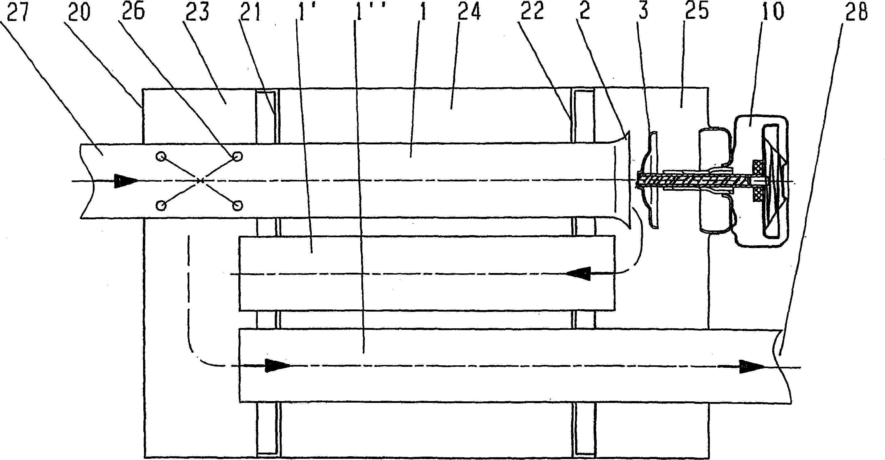
[0032] 1 and 2 both show schematically and in section an anechoic chamber 20 whose interior is divided into three chambers 23 , 24 , 25 by transverse partition members 21 , 22 . A pipe 27 brings the exhaust gas into the anechoic chamber 20; a pipe 28 takes the exhaust gas out of the anechoic chamber 20 again.

[0033] Inside the anechoic chamber 20, three pipes 1, 1', 1" carrying the exhaust gases can be seen. In the immediate vicinity of the first chamber 23, the pipes 1 have perforations 26 through which the exhaust gases can escape.

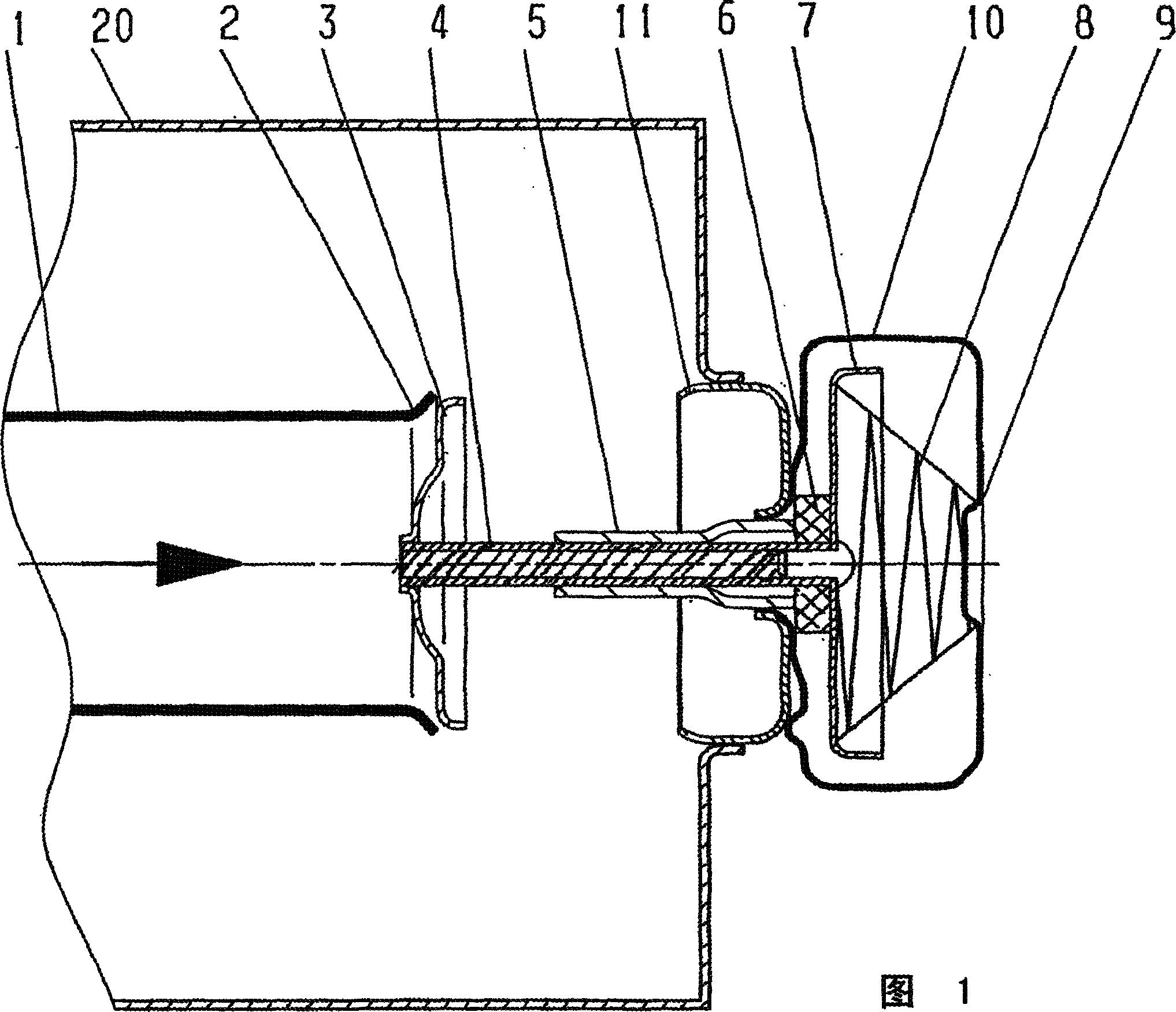
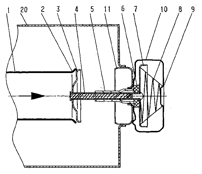
[0034] As shown enlarged in FIG. 1 , the end 2 of the first exhaust gas line 1 is conically widened. A valve disk 3 , which is also conical, closes off the end 2 of the line 1 . The valve disc 3 is mounted on a guide rod 4 , which guides movement in a guide sleeve 5 . The guide bush 5 is held by a fitting 11 airtightly mounted on the wall of the anechoic chamber 20 . Outside the anechoic chamber 20, a valve housing 10 can be seen. In the v...


PUM


Abstract

The Invention relates to mufflers with variable damping characteristic for motor vehicles with internal combustion engine, comprising a housing (20) with at least one gas pipe (1), terminating in the housing (20), and at least one valve whose closure element (3) closes the end (2) of the pipe (1) in rest position. The closure element (3) is a disk, seated on a guide rod (4). The guide rod (4) is guided in a guide sleeve (5) and performs a lifting mouvement. The spring (8) is positioned in a valve housing (10) which is gastight and connected in gastight manner to the muffler housing (20). As soon as the pressure in the gas pipe (1) is high enough, the valve disk (3) opens against the force of the spring (8).

Description

technical field [0001] The invention relates to a muffler with variable damping characteristics for motor vehicles. Background technique [0002] US4,484,659, US5,614,699 and US2002 / 0033303A all disclose mufflers with variable damping characteristics. All of these mufflers have an anechoic chamber into which the exhaust gas of the internal combustion engine enters via an inlet pipe and out of which exits via an outlet pipe. There are other pipes in the anechoic chamber. [0003] In addition, there is a valve in the anechoic chamber. The valve has a spring-loaded closing element which closes the exhaust opening in the static state, ie at low exhaust gas flow rates, for example when the internal combustion engine is idling. This forces the exhaust air to travel a long distance back and forth within the anechoic chamber, greatly damping noise disturbances. [0004] As the rotational speed of the internal combustion engine increases, the flow rate of the exhaust gas increase...

Claims


Application Information

Patent Timeline
Patent Type & Authority Applications(China)
IPC IPC(8): F01N1/02F01N1/08F01N1/16
CPCF01N1/084F01N1/166F01N1/165F01N1/16
Inventor D·维梅莱尔R·魏纳特A·欣科R·韦内齐亚诺P·罗布尔斯G·拉瓦尔格
Owner HEINRICH GILLET GMBH & CO KG
Why Eureka
Try Eureka