Stirling engine assembly

A Stirling engine and engine technology, which is applied in the direction of Stirling engine, machine/engine, hot gas variable capacity engine device, etc., can solve problems such as instability and achieve the effect of eliminating contradictions

Inactive Publication Date: 2004-09-22
MICROGEN ENGINE CORP HLDG BV
View PDF1 Cites 1 Cited by
  • Summary
  • Abstract
  • Description
  • Claims
  • Application Information

AI Technical Summary

Problems solved by technology

However, using a low stiffness mounting syst...

Method used


Image

  • Stirling engine assembly
  • Stirling engine assembly
  • Stirling engine assembly

Examples


Embodiment Construction

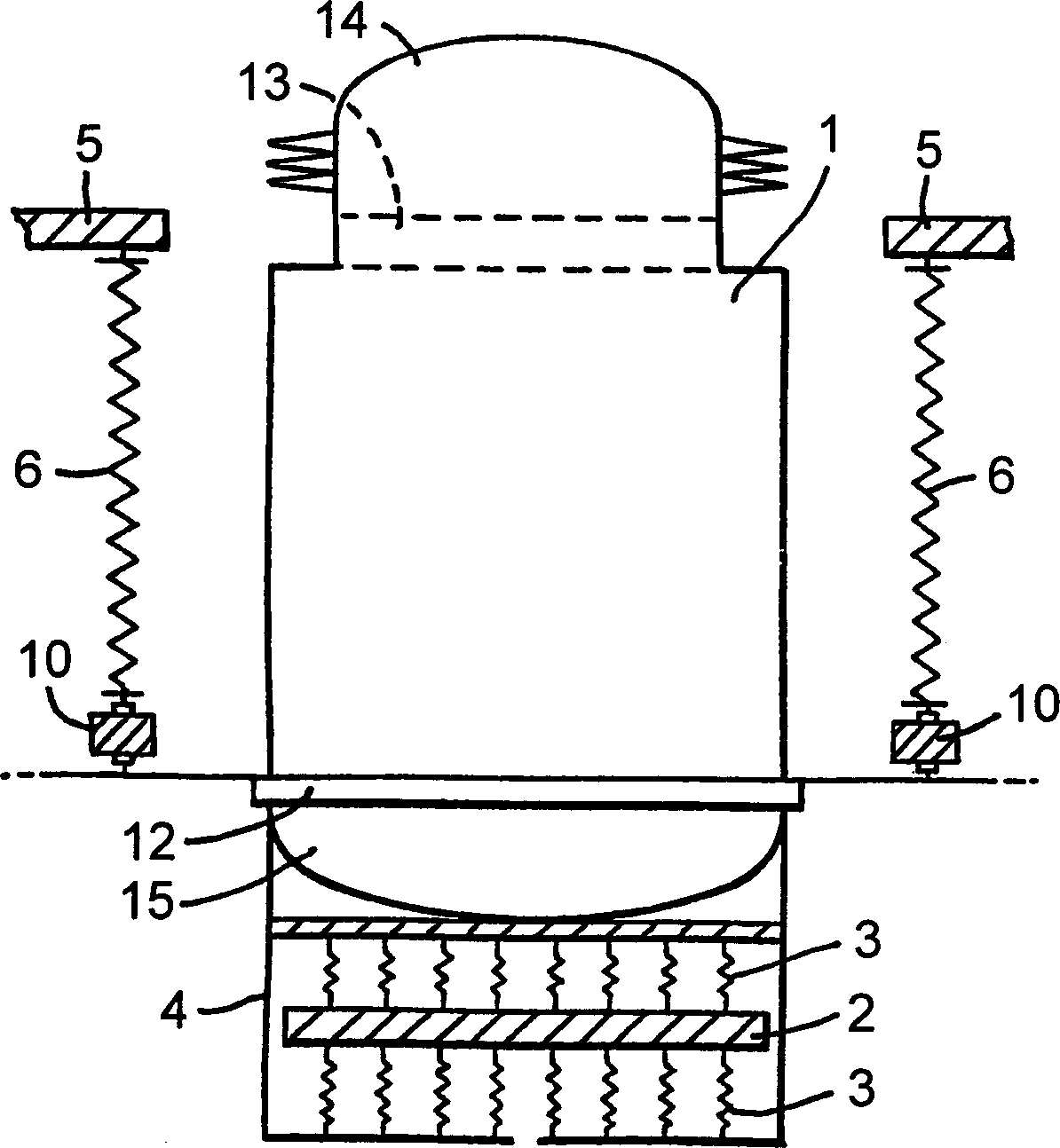
[0028] The Stirling engine assembly comprises a Stirling engine 1, which is well known in the art. The Stirling engine has a displacer and a power piston, both arranged to reciprocate in a vertical direction. This produces a net vertical vibration of the Stirling engine 1 itself.

[0029] In order to reduce this vibration, the damper mass 2 is supported by compression springs 3 above and below the damper mass 2 . This structure is housed in a casing 4 which is rigidly fixed to the bottom of the Stirling engine 1 . The mass 2 and spring 3 are adjusted such that the damper mass 2 vibrates as closely as possible in anti-phase to the Stirling engine 1 when the Stirling engine 1 is operating at the normal operating frequency. Thus, the overall vibration of the Stirling engine 1 and housing 4 is greatly reduced.

[0030] The current structure includes 8 compression springs 3 above and 8 compression springs 3 below the shock absorber mass 2 of 10.5 kg (±10%). For example, these s...


PUM

PropertyMeasurementUnit
Free lengthaaaaaaaaaa

Abstract

A Stirling engine assembly for a DCHP system. A Stirling engine (1) is suspended from a mounting frame (5) by a plurality of tension springs (6). An annular absorber mass (2) surrounds the Stirling engine and is suspended from the engine on a plurality of resilient members (3) arranged asymmetrically about the main axis. The asymmetric arrangement is provided by members of different stiffnesses, or irregular spacing of the members. The absorber mass (2) itself may be reduced adjacent to the resilient members.

Description

technical field [0001] The present invention relates to a Stirling engine assembly. In particular, the present invention relates to an assembly suitable for use in a combined domestic heat and power (DCHP) unit. Background technique [0002] Such domestic combined heat and power unit will be used in domestic environment instead of ordinary boiler. In this case, it is important to keep noise and vibration to a very low level so that it is acceptable to customers. [0003] Typically, the engine is supported by mounting it on springs that will isolate the vibrations that occur during normal engine operation. An example of a Stirling engine of this construction is US Pat. No. 4,400,941. In order to achieve the highest degree of isolation, a low stiffness mounting system is required. However, using a low stiffness mounting system with compression springs can lead to instability. Contents of the invention [0004] In accordance with the present invention, a Stirling engine ...

Claims


Application Information

Patent Timeline
IPC IPC(8): F02G1/043F16F7/104F16F15/04F16F15/08
CPCF16F7/104F16F15/046F02G1/0435F02G2243/20F16F15/085
Inventor 亚当·理查德·格雷戈里大卫·安东尼·克拉克朱莉·帕特丽夏·海德大卫·迈克尔·热纳维
Owner MICROGEN ENGINE CORP HLDG BV
Why Eureka
Try Eureka