Functional material fixing method and functional material fixing device

A technology of functional materials and fixing methods, applied in printing devices, lighting devices, optical/shielding devices, etc., can solve problems such as wiring disconnection, drying step taking a long time, reference line offset, etc.

Inactive Publication Date: 2004-09-29
SEIKO EPSON CORP
View PDF1 Cites 31 Cited by
  • Summary
  • Abstract
  • Description
  • Claims
  • Application Information

AI Technical Summary

Problems solved by technology

[0004] In order to eliminate these disadvantages, it has also been considered to use a nitrogen flow and an infrared lamp to dry the droplets adhering to the substrate, but the drying process takes a long time, resulting in low efficiency
In addition, due to the expansion of the substrate itself due to nitrogen flow and infrared lamps, the reference line may be shifted and the wiring formed on the substrate may be disconnected.
At the same time, due to the temperature rise of the environment, the flight trajectory of the droplet will bend in an unexpected direction, which may make it difficult to control the droplet ejection

Method used


Image

  • Functional material fixing method and functional material fixing device
  • Functional material fixing method and functional material fixing device
  • Functional material fixing method and functional material fixing device

Examples


Embodiment 1

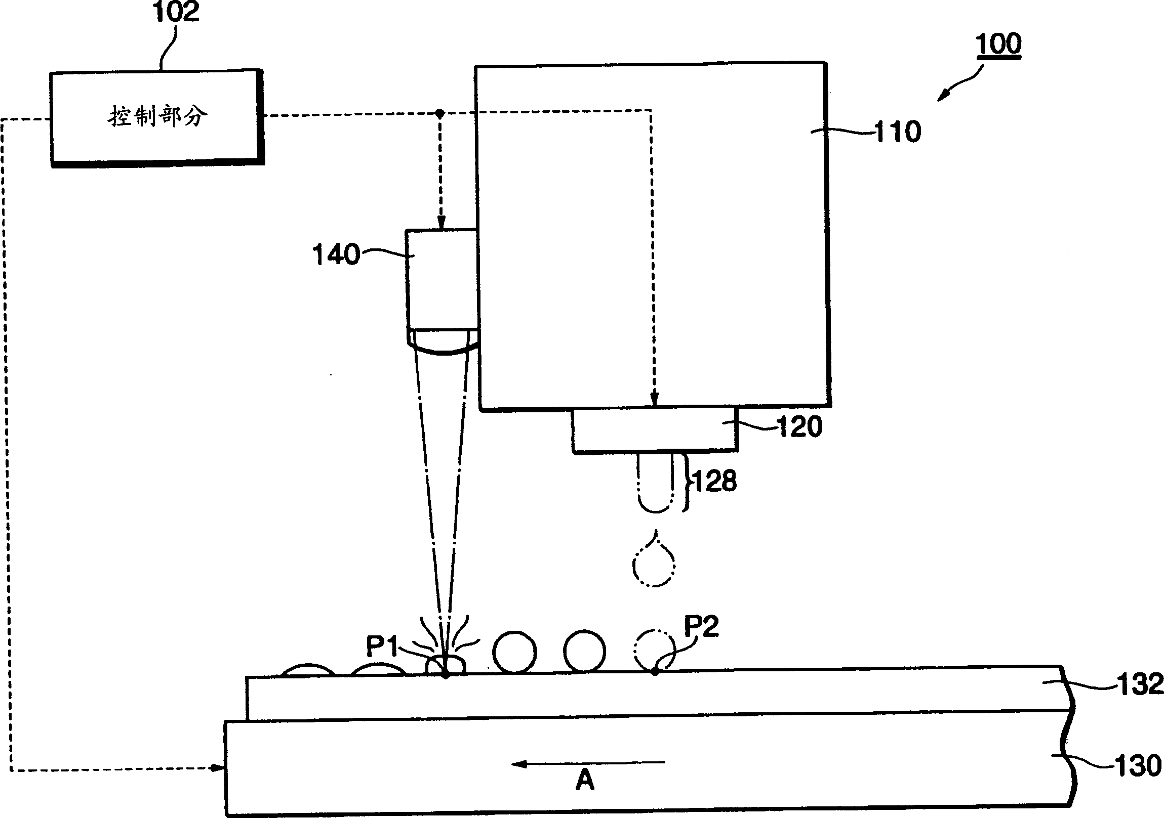
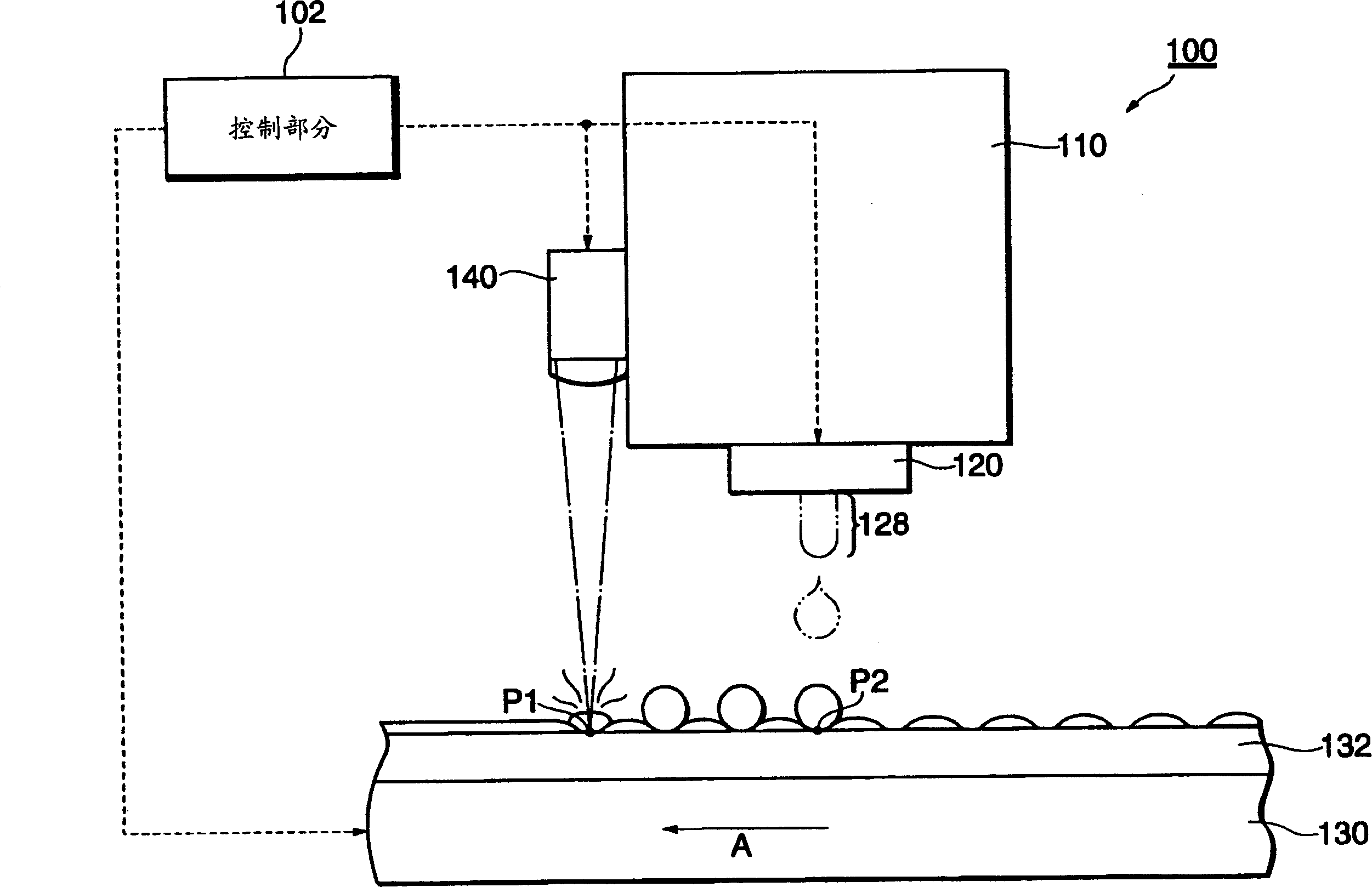
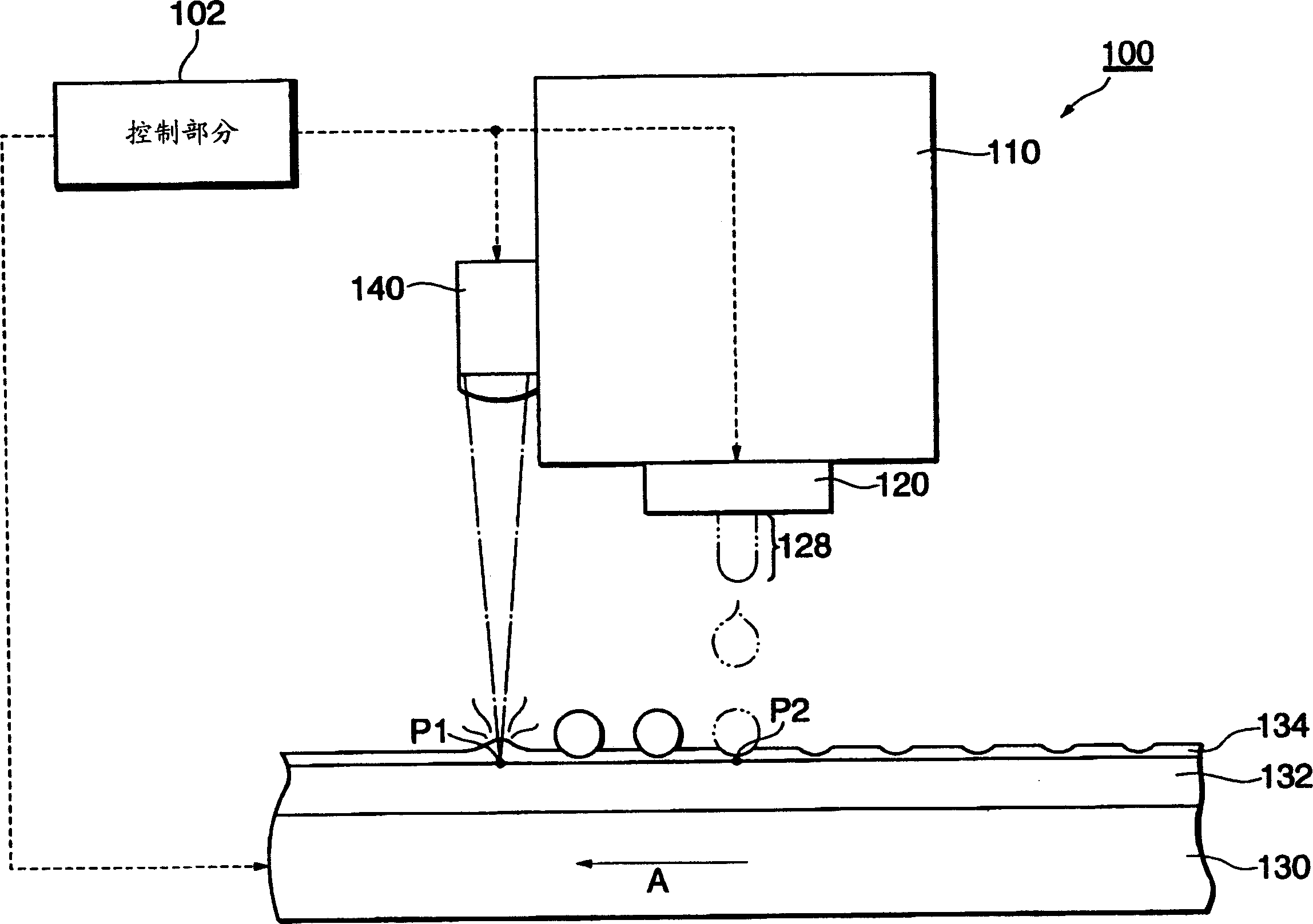
[0075] figure 1 It is a schematic diagram of the structure of the functional material fixing device 100 of the first embodiment.

[0076] According to the figure, the control unit 102 outputs drive signals to the ejection head 120, the base carriage 130, the laser source 140, and the actuator 170 to control the entire system. The control section 102 includes a CPU, a timer, a memory storing wiring patterns, and the like. The solution container 110 stores a solution with a viscosity of 20mpa·s, which is mixed with silver particles constituting the wiring material in C 14 h 30 (n-tetradecane: n-tetradecane) and other organic solutions (solvents). The ejection head 120 receives the solution supplied from the solution container 110 under the control of the control unit 102 , and ejects the solution into droplets.

[0077] The substrate carrier 130 transfers the substrate 132 in a horizontal direction corresponding to the ejection head 120 under the control of the control part ...

Embodiment 2

[0092] According to the first embodiment, the functional material fixing device 100 for immobilizing the liquid droplets by irradiating the liquid droplets with a low-intensity laser after applying them has been described. On the other hand, according to the second embodiment, a functional material fixing device that irradiates the droplet with laser light almost simultaneously with the application of the droplet to fix the droplet will be described. Among the configurations of the functional material fixing device of this embodiment, the same configurations as those of the above-mentioned first embodiment are denoted by the same symbols.

[0093] Figure 4 It is a schematic diagram of the structure of the functional material fixing device 200 of the second embodiment. As shown in the figure, compared with the functional material fixing device 100 of the first embodiment, this device 200 newly adds a reflector 180 on the optical path of the laser light. The reflector 180 ref...

Embodiment 3

[0099] According to the above-mentioned first embodiment, the functional material fixing device 100 for fixing the functional material by scanning the substrate 132 with respect to a set of the ejection head 120 and the laser light source 140 has been described. On the other hand, according to the third embodiment, a functional material fixing device that scans a substrate 132 with respect to two sets of jet heads and laser light sources will be described.

[0100] Figure 7 It is a schematic diagram of the structure of the functional material fixing device 300 of the third embodiment. As shown in the figure, this apparatus 300 includes a solution container 110 a located upstream in the transport direction A of the substrate and a solution container 110 b located downstream. Wherein, the solution container 110a is equipped with a spray head 120a and a laser source 140a. On the other hand, the solution container 110b is equipped with an ejection head 120b and a laser light so...


PUM


Abstract

It is an object of the present invention to provide a method for fixing a functional material with good accuracy in a prescribed position on a fixing surface. In order to attain this object, the present invention provides a method for fixing a functional material, comprising a droplet ejection step of ejecting a droplet of a functional material dispersed in a solvent onto a fixing surface, and a drying step of locally heating the droplet ejected on the fixing surface and gasifying part of the droplet by irradiating the droplet with a laser beam. According to this method, the droplet can be dried rapidly, heating of the entire substrate is suppressed, and loss of alignment or breakage of wiring or the like caused by the expansion of substrate can be avoided.

Description

technical field [0001] The present invention relates to a fixing technology of functional materials, in particular to an improved technology for fixing functional materials in desired positions precisely. Background technique [0002] A droplet discharge method is well known as one of methods for patterning wiring and the like. According to this wiring pattern manufacturing method, as described in Japanese Patent Application Laid-Open No. 2002-261048 (Japanese Patent No. 2002-261048 ), first, droplets containing conductive fine particles such as silver fine particles are sprayed on the adhesion surface of a wiring board or the like. On, coated in the form of wires. Then, after the liquid droplets coated on the substrate are naturally dried, they are heated and fired together with the substrate to form wiring. However, since the weight ratio of the silver microparticles contained in the solution is as low as 60%, the thickness of the solution is greatly reduced when the sol...

Claims


Application Information

Patent Timeline
Patent Type & Authority Applications(China)
IPC IPC(8): G02B5/20B05C5/00B05C9/14B05D1/26B05D3/06B41J2/01B41J11/00B41J13/00B41M3/00B41M7/00G02F1/13H01B13/00H01J11/20H01J11/22H01J11/44H01L21/288H01L21/3205H01L21/768H01L23/522H01L51/40H01L51/50H05B33/10H05B33/26H05K3/00H05K3/10H05K3/12
CPCH01L51/0004B41M7/00H01L21/288B41M7/009B41M3/006H05K3/125H05K2203/107H05K3/1283B41M7/0027B41M7/0081H10K71/13B41J13/00
Inventor 三浦弘纲吉沢昌宏尼子淳
Owner SEIKO EPSON CORP
Why Eureka
Try Eureka