Hydraulic bearing, main shaft motor with said hydraulic bearing and disc driver with said main shaft motor

一种液动、轴承的技术,应用在带有静止电枢和旋转磁体的同步电动机、机电装置、滑动接触轴承等方向,能够解决外部助振力耐性不足等问题,达到防止保持量不足、扩大适用范围、强化耐性的效果

Inactive Publication Date: 2004-09-29
NIDEC CORP
View PDF2 Cites 12 Cited by
  • Summary
  • Abstract
  • Description
  • Claims
  • Application Information

AI Technical Summary

Problems solved by technology

Although this structure of the capillary seal part makes the volume of the capillary seal part the same as Figure 4 Compared with the structure, it can be enlarged, but the capillary seal is still affected by the change of the gap dimension due to the axial vibration of the rotor, so the resistance to the external vibration boosting force when the rotor stops rotating is insufficient.

Method used


Image

  • Hydraulic bearing, main shaft motor with said hydraulic bearing and disc driver with said main shaft motor
  • Hydraulic bearing, main shaft motor with said hydraulic bearing and disc driver with said main shaft motor
  • Hydraulic bearing, main shaft motor with said hydraulic bearing and disc driver with said main shaft motor

Examples


Embodiment Construction

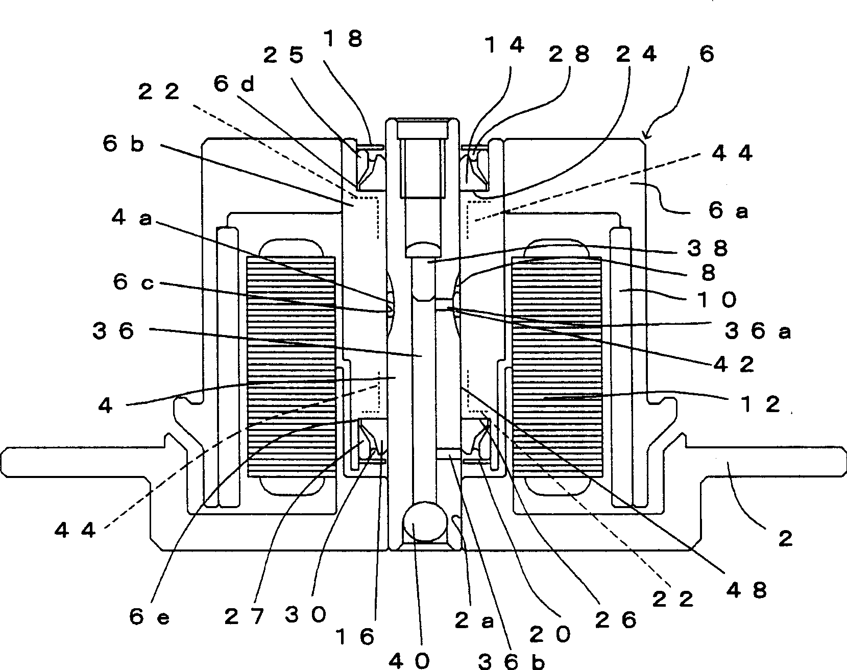
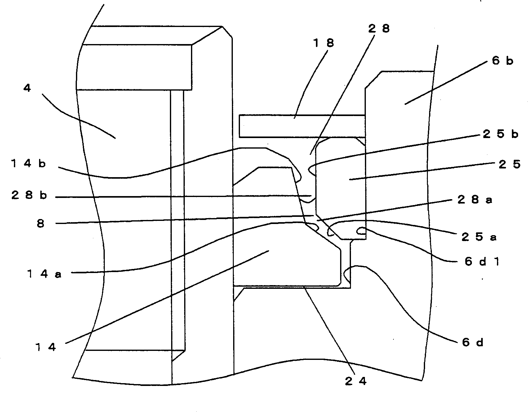
[0026] Below, refer to Figure 1 to Figure 3 ,and Figure 5 One embodiment of the fluid dynamic bearing of the present invention, a spindle motor using the fluid dynamic bearing, and a disk drive device including the spindle motor will be described. In addition, in one embodiment described in the present invention, the up-down direction in each drawing is referred to as "up-down direction" for convenience, but it is not used to limit the direction in the actual installation state.

[0027] figure 1 The shown spindle motor has: a bracket 2; a shaft 4 fixed on the bracket 2; a rotor 6 supported by the shaft 4 through a hydrodynamic bearing and relatively freely rotatable.

[0028] In the center of the bracket 2 as a stationary member, a center hole 2a in which one end of the shaft 4 is fitted and fixed is formed.

[0029] The rotor 6 as a rotating member includes: a sleeve 6b facing the shaft 4 via a hydrodynamic bearing; and a rotor hub 6a fitted and fixed to the outer peri...


PUM


Abstract

The present invention relates to a hydraulic bearing that supports a shaft and a sleeve for relative rotation with respect to a rotating shaft. In one example of the hydraulic bearing of the present invention, the capillary seal portion is formed continuously with the bearing portion that uses lubricating oil as the working fluid and is held by a minute gap. The capillary seal portion includes: a first capillary seal portion whose radial gap becomes at least larger as it moves away from the bearing portion toward the rotation axis; The second capillary seal portion has at least a larger radial gap away from the second capillary seal portion in the direction toward the rotation axis. The second capillary seal portion gradually expands toward the outer side in the axial direction.

Description

technical field [0001] The present invention relates to a hydrodynamic bearing (Hydrodynamic Bearing), a spindle motor using the bearing, and a disk drive device having the spindle motor. Background technique [0002] As a bearing for freely rotating a rotor (rotor) of a spindle motor used in a disk drive device such as a hard disk drive, fluid dynamic bearings capable of achieving quiet, low-vibration, and stable rotation have begun to be used. [0003] As such a fluid dynamic bearing, there is, for example, US Pat. No. 5,423,612. Figure 4 A partially enlarged cross-sectional view showing a partial schematic structure of the aforementioned US Patent No. 5,423,612. [0004] The thrust plate 102 is fixed on the fixed shaft 100, and is held between the outer peripheral surface of the fixed shaft 100 located below the axial direction of the thrust plate 102 and the inner peripheral surface of the rotor 104 opposite to the outer peripheral surface in the radial direction as a w...

Claims


Application Information

Patent Timeline
Patent Type & Authority Applications(China)
IPC IPC(8): F16C17/10F16C33/10F16C33/74G11B19/20H02K7/08H02K21/22
CPCF16C33/74G11B19/2018F16C17/107F16C2370/12F16C33/107F16C33/103F16C33/745
Inventor 奥义人松本祐介
Owner NIDEC CORP
Why Eureka
Try Eureka