
Valve opened of control valve core by magnetic suspension method

A technology to control the valve core and magnetism, which is applied in the direction of valve operation/release device, sliding valve, valve details, etc., can solve the problems of sealing ring wear, leakage of the joint between the shaft and the valve body, etc., and achieve long service life and overall structure Simple, Small Effects

Inactive Publication Date: 2004-10-20
卢大明
View PDF0 Cites 0 Cited by
  • Summary
  • Abstract
  • Description
  • Claims
  • Application Information

AI Technical Summary

Problems solved by technology

Compared with the traditional valve, the service life of the above-mentioned valve has been improved many times, but because the connecting part of the shaft and the valve body is sealed by an O-ring or a rubber pad, the sealing ring is still worn when the valve is switched on and off, causing the shaft to Leakage occurs at the connection with the valve body

Method used


Image

  • Valve opened of control valve core by magnetic suspension method
  • Valve opened of control valve core by magnetic suspension method
  • Valve opened of control valve core by magnetic suspension method

Examples


Embodiment Construction

[0013] The structure of the present invention will be further described in detail below in conjunction with the drawings and embodiments.

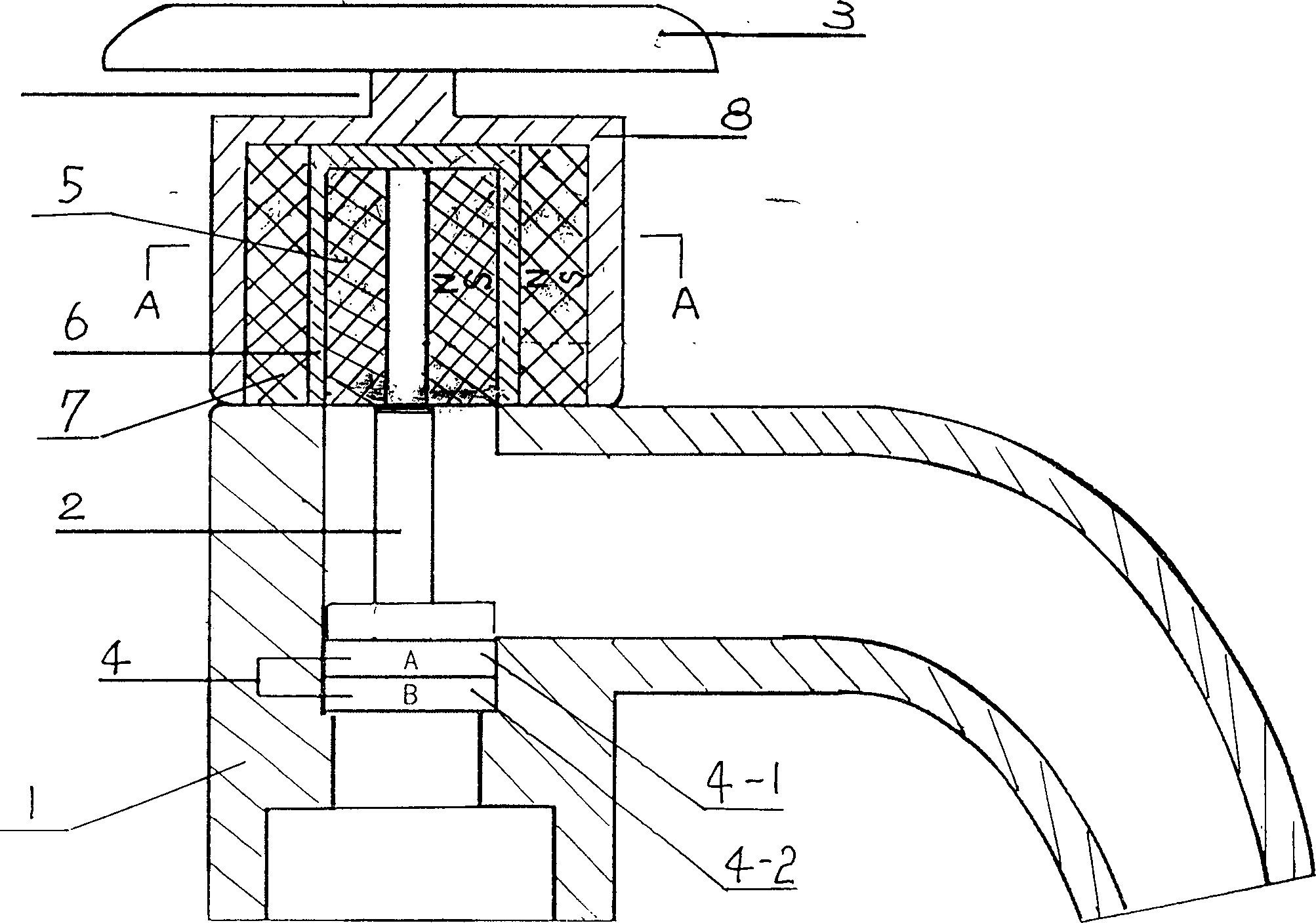
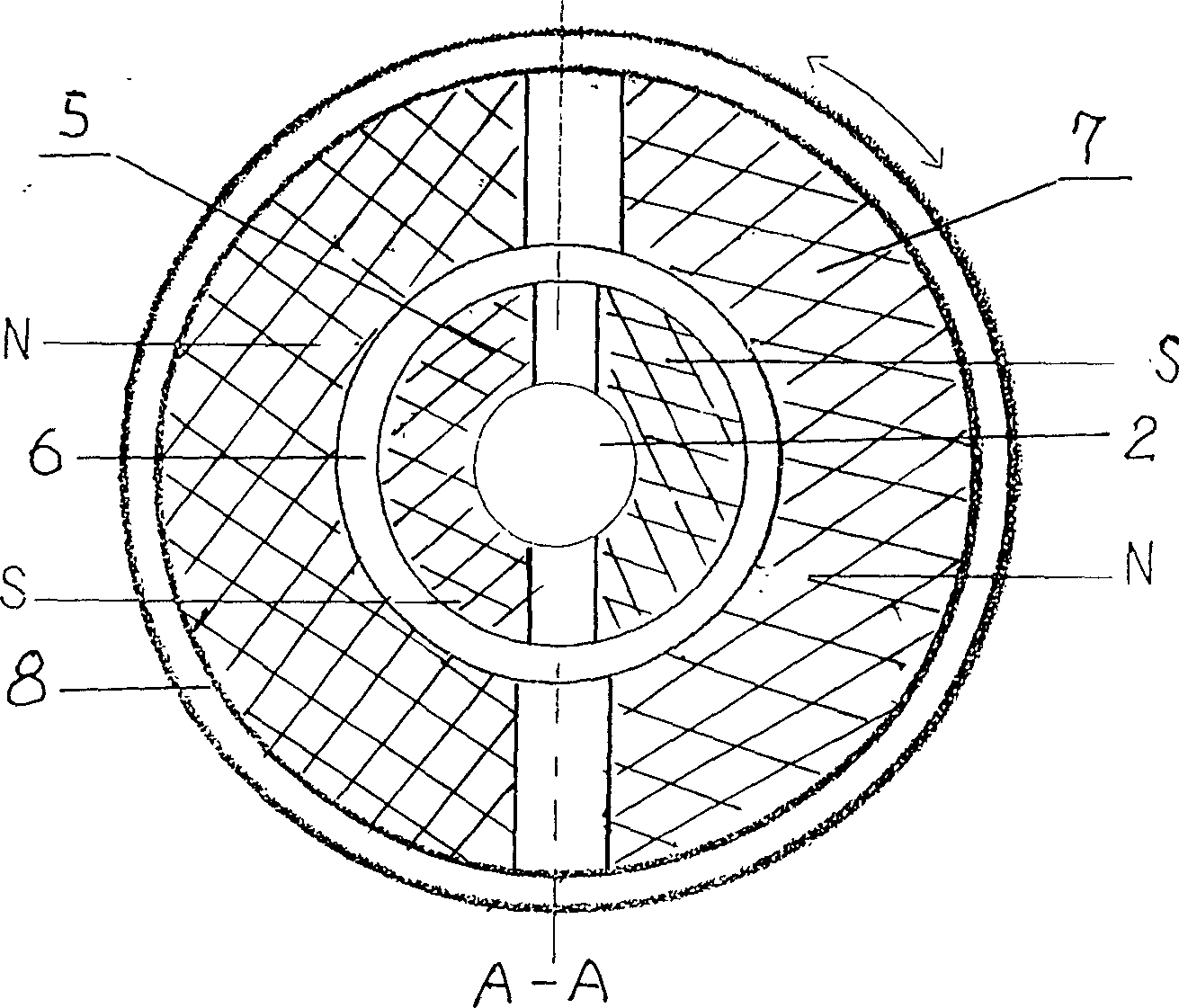
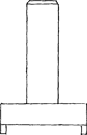
[0014] Refer to attached Figure 1-5 , the valve that uses the magnetic suspension method to control the opening of the valve core mainly includes a valve body 1, a central shaft 2, a handle 3, and a valve core 4, and is characterized in that the valve core is composed of a moving piece 4-1 with a water outlet and a fixed valve core. The fixed piece 4-2 is bonded to the valve body 1, and the moving piece 4-1 is bonded to the rectangular fork at the lower end of the central shaft 2. The upper part of the central shaft 2 is provided with an inner magnet 5. The outer edge of the inner magnet is sleeved in the inner and outer magnetic isolation sleeve 6, and is threadedly connected with the valve body. The outer surface of the isolation sleeve 6 is provided with an outer magnet 7 placed at a position corresponding to the opposite pole of the i...


PUM


Abstract

A valve whose valve core is opened by magnetic suspending method features that its handle, central axle of valve body and valve core are connected indirectly, that is, connected in magnetic suspending mode, resulting in no leakage, small size and long service life.

Description

technical field [0001] The invention belongs to a valve, in particular to a valve which uses a magnetic levitation method to control the opening of a valve core. Background technique [0002] Existing various switching valves, its valve core adopts metal parts such as cast iron, iron copper and rubber parts to be combined mostly. When in use, dripping occurs due to easy wear and aging of rubber parts, and the service life is very short. A valve that can be used tens of thousands of times has been introduced on the market. Its structure is composed of a valve body, a valve core and a rotating shaft. For the moving piece, the upper and lower fixed pieces are penetrated with a water cavity and separated by a spacer. The moving piece has a non-through water cavity and is separated by a spacer. The moving piece is embedded by the rotating shaft. By rotating with a fixed handle, the upper fixed piece There is an O-ring on it, which is pressed by the gland. By changing the relat...

Claims


Application Information

Patent Timeline
Patent Type & Authority Applications(China)
IPC IPC(8): F16K3/08F16K31/08
Inventor 卢大明
Owner 卢大明
Learn More