A two-way air-tight drill pipe joint with tensile bending resistance
What is Al technical title?
Al technical title is built by PatSnap Al team. It summarizes the technical point description of the patent document.
A technology for drill pipe joints and air sealing, which is applied in the direction of drill pipes, drill pipes, drilling equipment, etc., can solve the problems of shoulder surface separation, seal failure, erosion corrosion, etc., and achieve excellent bending resistance, improved sealing reliability, The effect of ensuring reliability
Active Publication Date: 2017-02-22
EAST CHINA UNIV OF SCI & TECH +3
View PDF1 Cites 0 Cited by
Summary
Abstract
Description
Claims
Application Information
AI Technical Summary
This helps you quickly interpret patents by identifying the three key elements:
Problems solved by technology
Method used
Benefits of technology
Problems solved by technology
In this regard, the API joint adopts a sealing form in which single shoulders squeeze each other. This structure only seals the outer annulus and fails to prevent the internal high-temperature and high-pressure drilling fluid from eroding the thread teeth. At the same time, tensile and bending loads will cause platform Shoulder separation, rendering seal ineffective
[0003] In order to improve the sealing performance of the joint, the American Grant Company developed and designed the double-shoulder joint, but it still failed to effectively solve the leakage problem caused by the tensile load; the patent CN201826771U added a metal cone sealing structure at one end of the double-shoulder, which improved The sealing performance of the inner shoulder, but the drilling fluid can still erode the sealing cone surface through the gap of the inner shoulder, and the life of the sealing structure cannot be effectively guaranteed
At the same time, under the action of bending load, the outer shoulder has a tendency to open, which will also cause leakage
Method used
Image
Click on the blue label to locate the original text in one second.
Reading with bidirectional positioning of images and text.
Examples
Embodiment Construction
[0026] The present invention is described in detail by the following examples. It should be pointed out that the following examples are only to further illustrate the present invention, and can not be interpreted as limiting the protection scope of the present invention. Those skilled in the art make according to the content of the present invention Some non-essential improvements and adjustments still belong to the protection category of the present invention.
[0027] see Figure 1 to Figure 6 ,in figure 1 A schematic diagram of an API NC38 tool joint is shown.
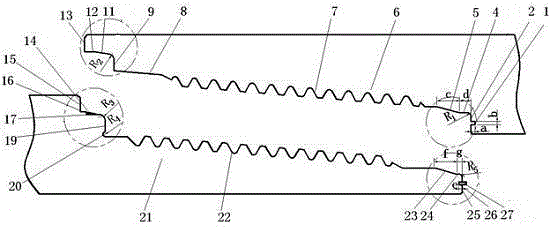
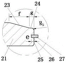
[0028] figure 2 Shown is a schematic diagram of the structure of the anti-bending two-way gas-sealed drill pipe joint of the present invention, which is composed of an internal threaded part 6 and an external threaded part 21 . It is characterized in that the internal threaded part 6 includes a first outer shoulder surface 13, a first cylindrical hole 12, a first conical hole 11 matched with a wedge-shaped rubbe...
PUM
Abstract
The invention relates to an anti-stretching-bending bidirectional air-tight seal tool joint. The anti-stretching-bending bidirectional air-tight seal tool joint consists of an inner threaded workpiece and an outer threaded workpiece, wherein the inner threaded workpiece comprises a first outer circular bead surface, a first cylindrical hole, a conical hole matched with a wedge-shaped rubber ring, a second outer circular bead surface, a conical hole, an outer thread, an inner thread large-end sealing conical surface, a second cylindrical hole, an inner circular bead surface and an inner thread sealing ring groove; the inner circular bead surface and the second cylindrical hole as well as the second outer circular bead surface and the conical hole are in transition connection in sequence; the outer threaded workpiece comprises a wedge-shaped rubber sealing ring, a first outer circular bead surface, a first cylindrical surface, a rubber sealing ring mounting cylindrical surface, a second outer circular bead surface, a stress relieving groove, an outer thread, an outer thread nose end sealing conical surface, a second cylindrical surface, an inner circular bead surface, an outer thread sealing ring groove and a metal sealing ring. The anti-stretching-bending bidirectional air-tight seal tool joint has inner and outer sealing structures, and bidirectional sealing can be realized for the joint after engagement of the inner and outer threads, so that the sealing reliability of a drilling string system under stretching and bending loads is enhanced, and very high air-tight performance is achieved; the anti-stretching-bending bidirectional air-tight seal tool joint is suitable for exploiting oil and gas resources under the complex well conditions of high pressure wells, ultrahigh pressure wells, directional wells, large displacement wells, horizontal wells and the like.
Description
technical field [0001] The invention belongs to the technical field of threaded connection of oil well pipes, and relates to a drill pipe joint for oil and natural gas development, in particular to a tensile-bending two-way gas-sealed drill pipe joint. Background technique [0002] Drill pipes are connected by drill pipe joints to transport drilling fluid. Therefore, the drill pipe joints should have good liquid sealing performance. At the same time, due to the needs of well logging, higher requirements are put forward for the air sealing performance of the joints. . Due to the structure of the traditional threaded joint, there is a spiral leakage channel between the meshing teeth, which is mainly sealed by thread grease, but because the leakage channel is not effectively blocked, the thread grease will flow out, and the high temperature and high pressure will significantly reduce its sealing. performance. In this regard, the API joint adopts a sealing form in which single...
Claims
Application Information
Patent Timeline
Application Date:The date an application was filed.
Publication Date:The date a patent or application was officially published.
First Publication Date:The earliest publication date of a patent with the same application number.
Issue Date:Publication date of the patent grant document.
PCT Entry Date:The Entry date of PCT National Phase.
Estimated Expiry Date:The statutory expiry date of a patent right according to the Patent Law, and it is the longest term of protection that the patent right can achieve without the termination of the patent right due to other reasons(Term extension factor has been taken into account ).
Invalid Date:Actual expiry date is based on effective date or publication date of legal transaction data of invalid patent.