

Multifunctional tractor of cervical vertebrae and lumbar vertebra
A technology of cervical traction and cervical and lumbar traction, which is applied in the field of multifunctional cervical and lumbar traction machines, can solve problems such as aggravated pain, incomplete treatment, and aggravated pain, so as to improve tolerance, improve traction safety, and increase safety factor. Effect
- Summary
- Abstract
- Description
- Claims
- Application Information
AI Technical Summary
Problems solved by technology
Method used
Image

Examples
Embodiment Construction
[0030] The present invention is described in detail below in conjunction with accompanying drawing:
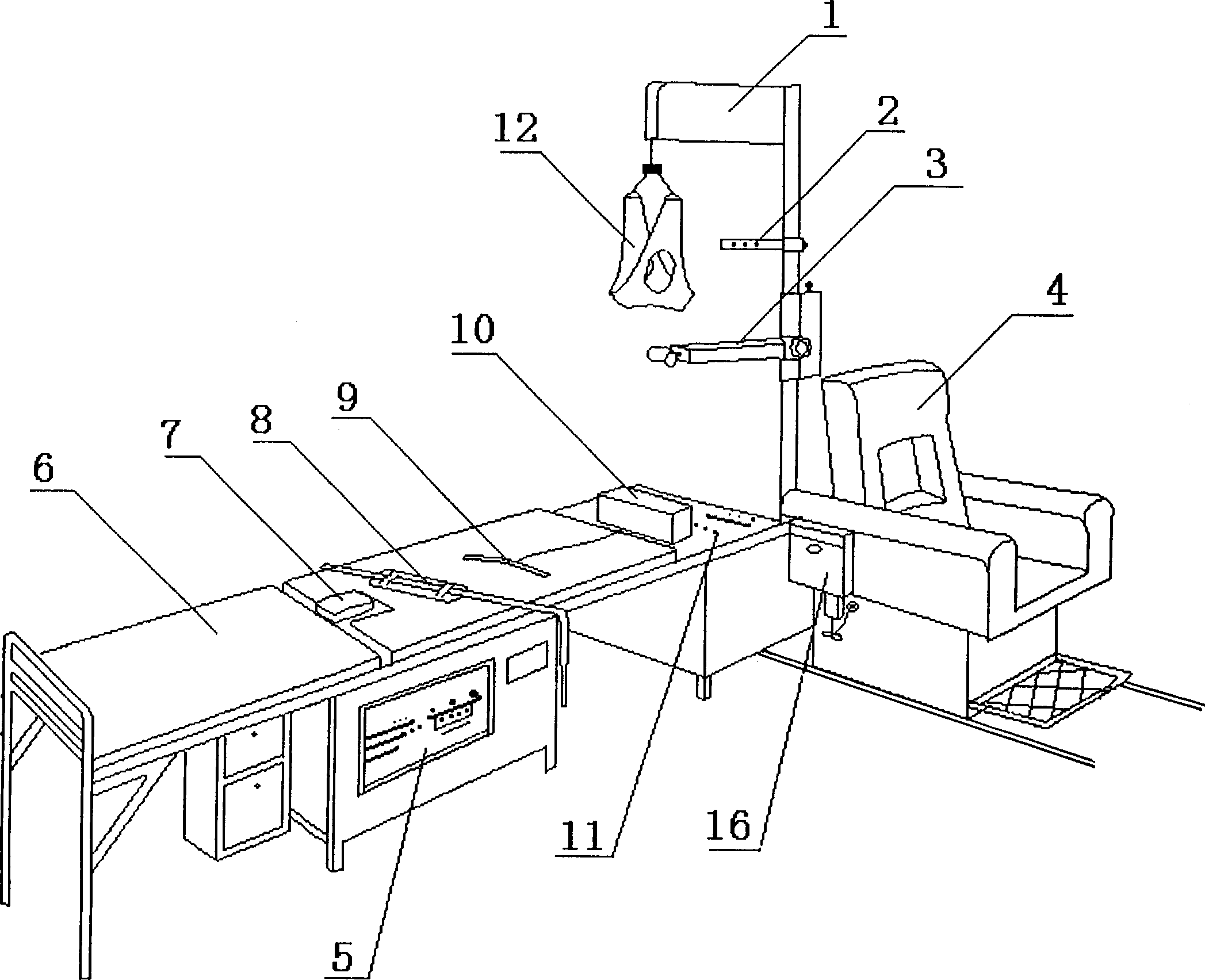
[0031] attached figure 1 For the overall connection schematic diagram of the present invention, be fixed on the column 14 on the mechanical control box 11, be equipped with cervical traction transverse arm 1, angle conversion device 2 and reset physical therapy device 3, chair 4 is at the lower end of column 14, and mechanical control box 11 is connected on The end of bed 6, the middle part of bed 6 has reset support 7, and its lower end is the mechanical control box 5 of control reset support 7 motions, and the lower end of chair 4 is equipped with manual pulley, can move forward and backward when carrying out semi-recumbent position traction.
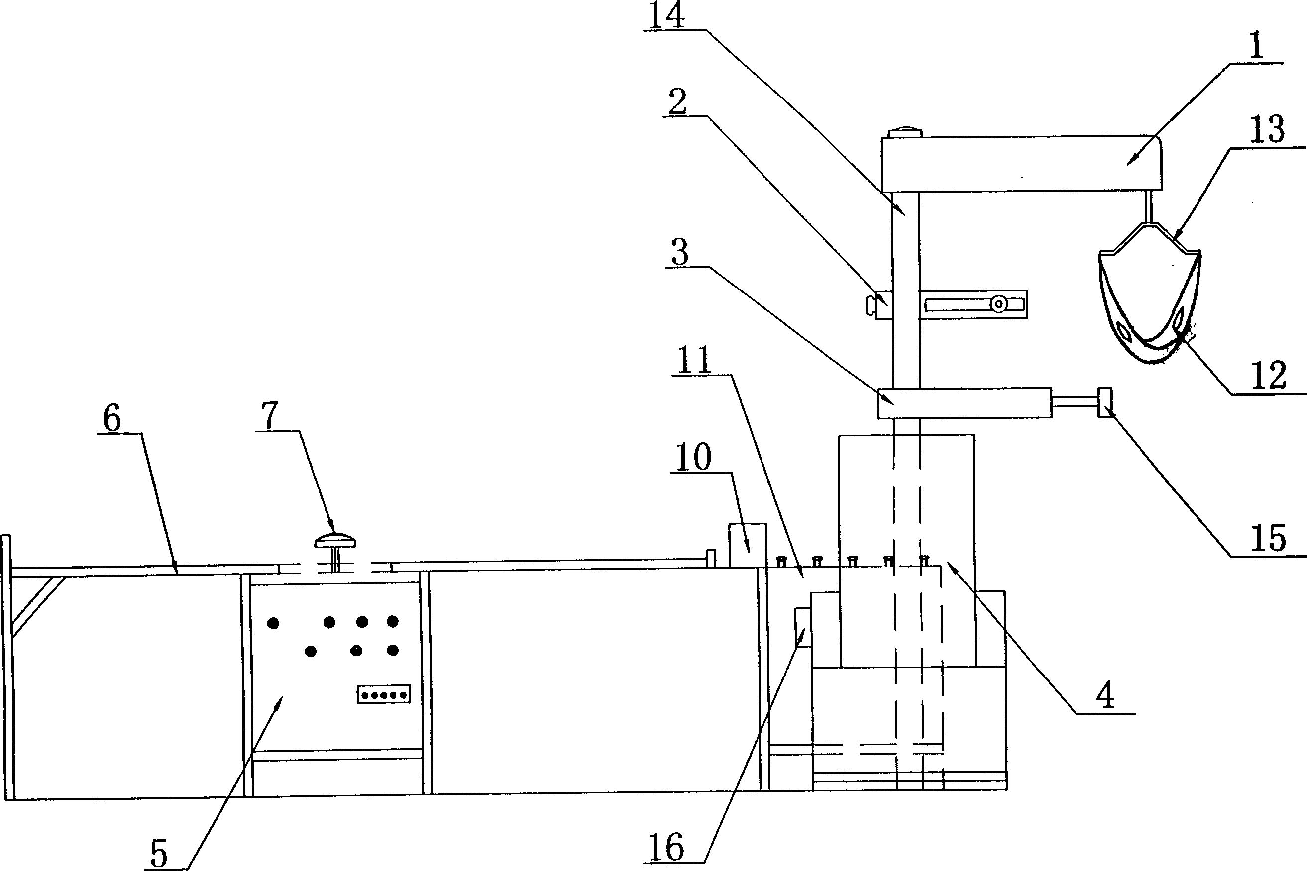
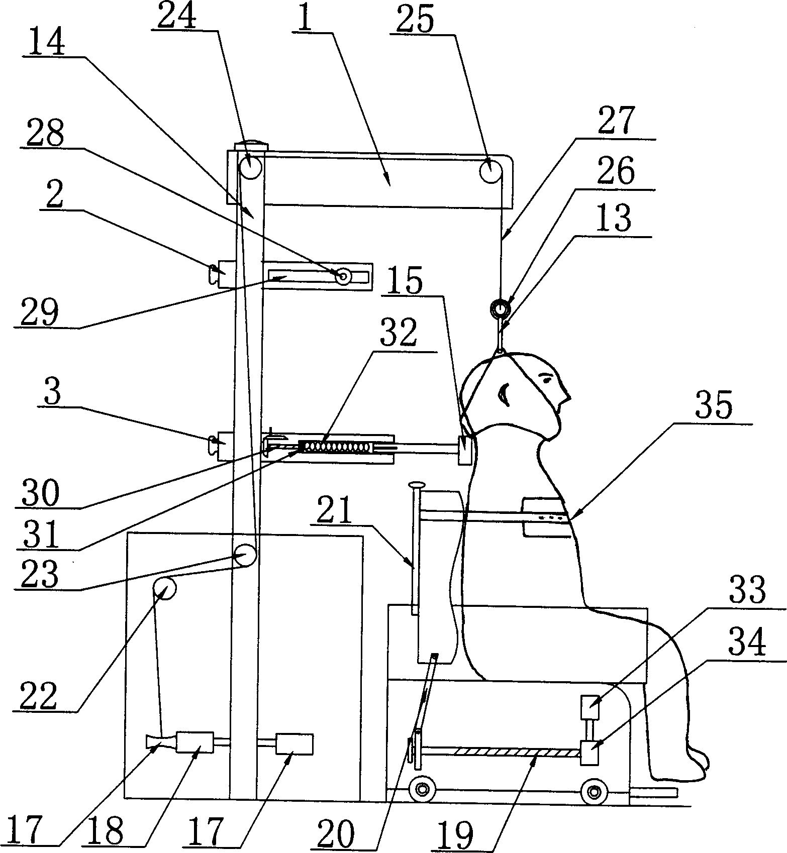
[0032] attached figure 2 And attached image 3 The shown cervical traction treatment device comprises a chair 4 with an adjustable backrest and a cervical traction cross arm 1, an angle changing device 2 and a reset physical therap...
PUM
 Abstract
Description
Claims
Application Information