Method for distributing power for hybrid power system of fuel cell

A technology of fuel cell system and hybrid power system, which is applied in electric traction, electric vehicles, control drive, etc., and can solve problems such as vehicle performance impact and system output power reduction

Inactive Publication Date: 2004-10-27
TSINGHUA UNIV
View PDF2 Cites 57 Cited by
  • Summary
  • Abstract
  • Description
  • Claims
  • Application Information

AI Technical Summary

Problems solved by technology

This actually reduces the output power capability of the system, and the perf

Method used


Image

  • Method for distributing power for hybrid power system of fuel cell
  • Method for distributing power for hybrid power system of fuel cell
  • Method for distributing power for hybrid power system of fuel cell

Examples


Embodiment Construction

[0037] The specific embodiment of the present invention will be described with reference to the accompanying drawings.

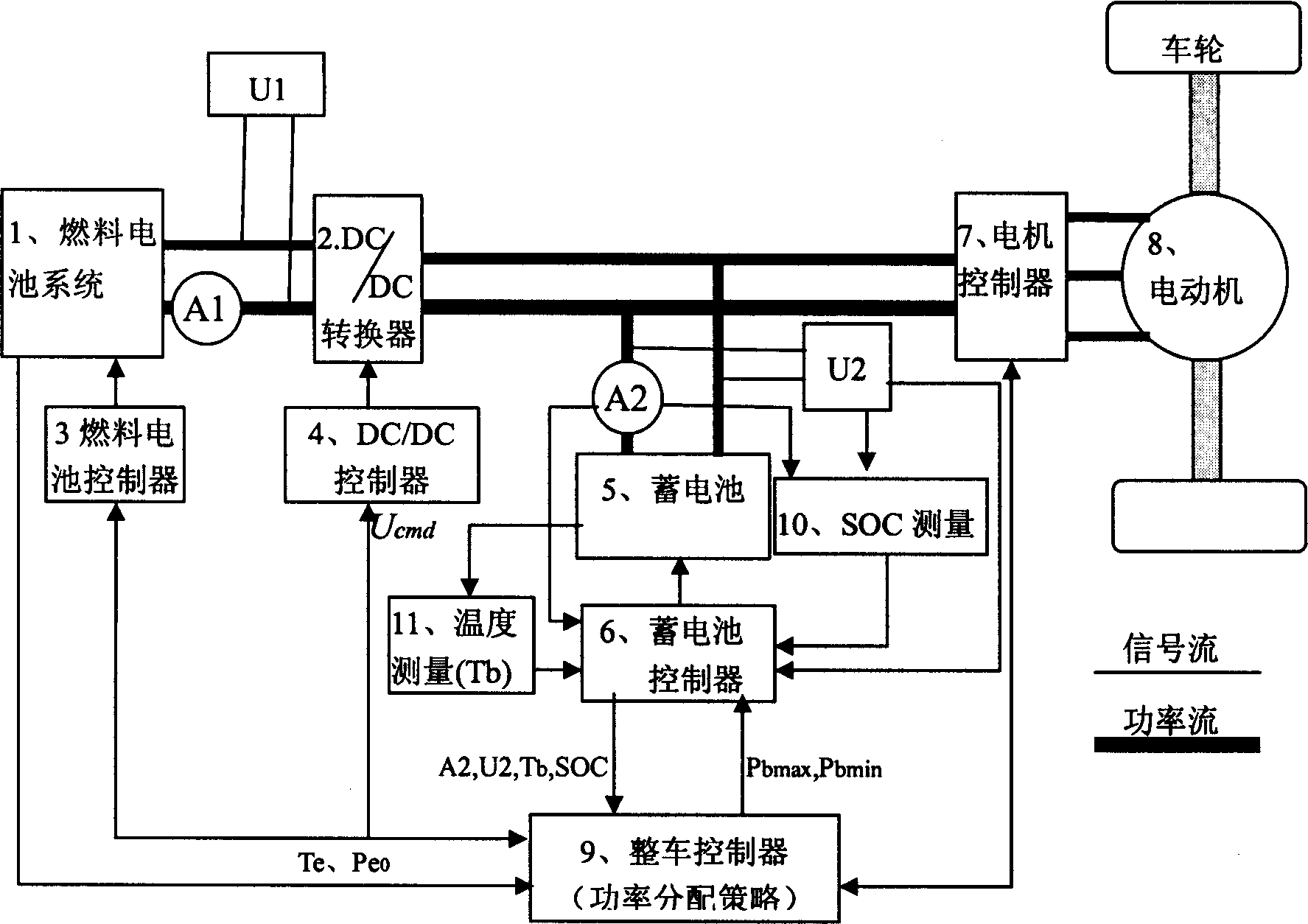
[0038] The structure of the power drive system of the fuel cell hybrid vehicle of the present invention is as follows: figure 1 As shown, the energy source is composed of a fuel cell system 1 and a storage battery 5 . During the running of the vehicle, the fuel cell system 1 provides the main energy required by the vehicle, and the storage battery 5 serves as an auxiliary energy system to provide insufficient power or absorb excess power. In addition, with figure 1 The current sensor A1 in the current sensor is used to measure the output current of the fuel cell, U1 is used to measure the output voltage of the fuel cell, A2 is used to measure the output current of the battery, U2 is used to measure the output voltage of the battery, and the SOC measuring device 10 is based on the measured values ​​of A2 and U2. Get the battery SOC. The function of the bat...


PUM


Abstract

A powder distributing method for the fuel battery and accumulator mixed power system includes determining the respective locally optimal power distributions for fuel battery and accumulator, and optimal power regulation for whole system for optimal power distribution.

Description

technical field [0001] The power distribution method of a fuel cell hybrid power system relates to the technical field of power optimization design of a fuel cell hybrid power system. Background technique [0002] With the growing awareness of environmental protection, more and more people in the automotive field are turning their attention to zero-emission fuel cell vehicles. However, due to the technology of the fuel cell system itself, fuel cell vehicles have not been gradually developed until the past two years. Because the dynamic characteristics of fuel cells are difficult to meet the frequent load changes of fuel cell vehicles, it is necessary to use batteries as system energy compensation devices in fuel cell vehicles. In such a power system composed of two energy sources, how to reasonably distribute power and optimize system efficiency is a major problem facing the development of fuel cell vehicles. [0003] In the patent US 2002 / 0095247 A1 published by the Unite...

Claims


Application Information

Patent Timeline
IPC IPC(8): B60L11/18B60L15/28
CPCY02T10/7275Y02T10/70Y02T10/72
Inventor 朱元田光宇吴昊周伟波陈全世欧阳明高
Owner TSINGHUA UNIV
Why Eureka
Try Eureka