Internal inserts in cooling towers

A cooling tower, plug-in technology, applied in water shower coolers, lighting and heating equipment, coatings, etc., can solve the problems of increasing blowers, increasing costs, increasing operating costs, etc., to reduce pollution and reduce costs.

Inactive Publication Date: 2004-10-27
SPX COOLING TECH
View PDF0 Cites 0 Cited by
  • Summary
  • Abstract
  • Description
  • Claims
  • Application Information

AI Technical Summary

Problems solved by technology

Partial clogging of the cross-section of the cooling insert through which the water and cooling air flow not only reduces efficiency but also increases costs due to the need for cleaning and also increases operating costs as the cooling tower pushes the air through the blower because Increased blower efficiency is necessary in order to pump the required sufficient cooling air through the cooling tower

Method used


Image

  • Internal inserts in cooling towers

Examples


Embodiment Construction

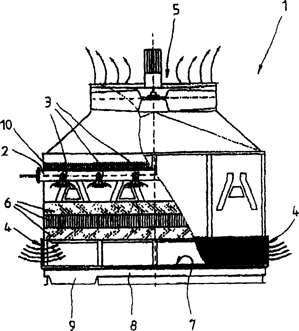
[0023] The figure shows a counterflow cooling tower 1 . The water heated to about 35° C.-40° C. during cooling enters the cooling tower 1 through the pipe 2 and is evenly distributed in the cooling tower 1 through a plurality of nozzles 3 . The air used to cool the water enters the inner space of the cooling tower 1 through the air inlet 4 and is forced through the cooling tower 1 in the opposite direction of the drip flow by the action of the blower 5 .

[0024] Due to the effect of the nozzle 3, the water is sprayed onto the cooling insert 6 like "rain". The cooling insert 6 comprises interconnected drip grids or drip blocks made of plastic. The trickle grid or blocking block forms a three-dimensional network of narrow meshes, and the purpose is to make the trickle drip as slowly as possible in the lattice structure of the cooling insert 6 .

[0025] The cooling insert 6 is swept over by the air flowing in the opposite direction. The water droplets that adhere to the latt...


PUM


Abstract

Building parts in the moist / wet region of cooling towers prepared from synthetic plastics to which are added additives in suitable amount to prevent subsequent growth of microorganisms.

Description

technical field [0001] The present invention primarily relates to internal inserts made of plastic located in the wet / wet area of ​​cooling towers. Cooling towers are used in various industrial fields to cool water. The cooling water heated up during the cooling process is introduced into the cooling tower and is uniformly distributed in the cooling tower through a plurality of openings of the duct system, for example with the aid of spraying devices or nozzles. As a result of the process described above, the water to be cooled trickles from above over the so-called cooling inserts and flows slowly through them. The cooling air used to cool the water is supplied from the other end of the cooling tower. Through evaporation and convection, the water transfers heat to the air passing through the cooling tower. The water cooled in this way is collected under the cooling insert and leaves the cooling tower via collectors and pipes. The cooled water is used for an additional coo...

Claims


Application Information

Patent Timeline
Patent Type & Authority Applications(China)
IPC IPC(8): F28C1/00F28F21/06F28F25/08
CPCF28F25/08F28F21/06Y10S261/46Y10S261/11F28F2265/20F28F2245/08F28C1/00
Inventor 马丁·金博克米罗斯拉夫·波德霍斯基
Owner SPX COOLING TECH
Why Eureka
Try Eureka