

PLL circuit and TV receiver using it, and improvement in beat of TV receiver
A TV receiver and receiver technology, applied to color TV parts, TV system parts, discontinuous tuning with a separate pre-tuning circuit, etc., can solve image quality deterioration, video frequency characteristics are different, etc. question
- Summary
- Abstract
- Description
- Claims
- Application Information
AI Technical Summary
Problems solved by technology
Method used
Image

Examples
Embodiment Construction
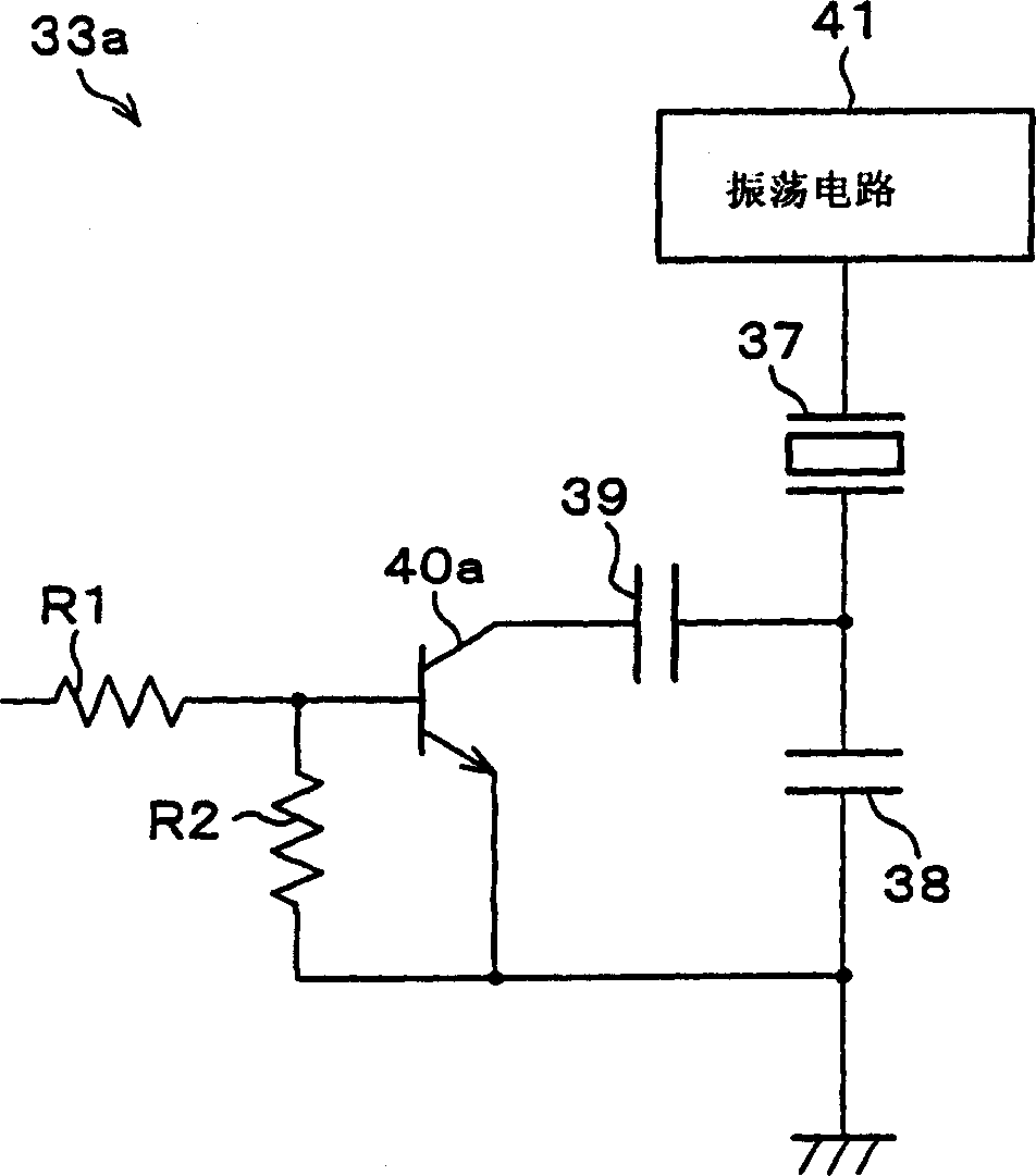
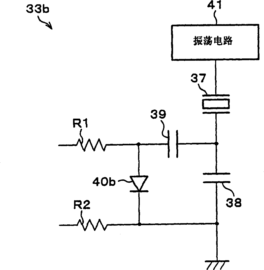
[0025] According to Figure 1 to image 3 , an embodiment of the present invention will be described as follows.
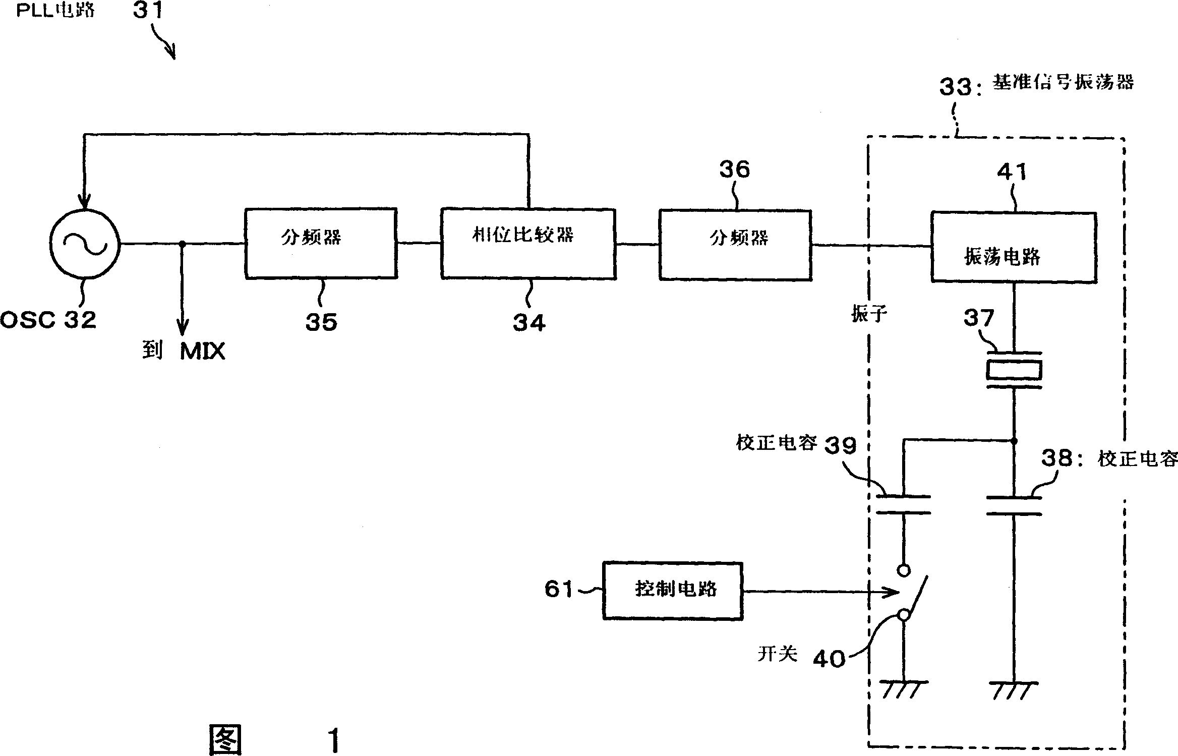
[0026] FIG. 1 is a block diagram showing the electrical configuration of a PLL circuit 31 according to an embodiment of the present invention. The configuration of this PLL circuit 31 includes an oscillator 32 that oscillates the LO signal, a reference signal oscillation circuit 33 , a phase comparator 34 , and frequency dividers 35 and 36 . The oscillator 32 is realized by a voltage-controlled oscillator or the like that oscillates at a frequency corresponding to the DC control voltage given by the phase comparator 34 .
[0027] The LO signal component generated by the oscillator 32 and the reference signal component generated by the reference signal oscillating circuit 33 are frequency-divided by respective frequency dividers 35 and 36, and the frequency-divided components are compared with each other in the phase comparator 34 to change the frequency. Feedback...
PUM
 Abstract
Description
Claims
Application Information