Spring balancer

A spring balancer and coupling technology, applied in the field of spring balancers, can solve the problems of reduced operating efficiency, entanglement of hoses, complicated hoses, etc.

Inactive Publication Date: 2004-11-03
ENDO IND
View PDF0 Cites 8 Cited by
  • Summary
  • Abstract
  • Description
  • Claims
  • Application Information

AI Technical Summary

Problems solved by technology

[0006] However, when the above-mentioned conventional spring balancer is used to suspend and hold the air tool with the installation torque detection function, the air tool is suspended by the spring balancer, and the hose for supplying compressed air and the hose for supplying compressed air must be separately installed and connected. Hose that transmits air pressure signal Bonded double hose, etc.
[0007] In addition, when using the above-mentioned conventional spring balancer for air tools to suspend and hold an air tool with a mounting torque detection function, it is necessary to separately install and connect coiled hoses for transmitting air pressure signals, etc.
[0008] Therefore, in either case, it is complicated to install a separate hose, and the hoses may become entangled between adjacent air tools during work, etc.
Therefore, there is a problem that the securing of working space and the like and the improvement of the working environment cannot be sufficiently realized, and as a result, working efficiency is lowered.

Method used


Image

  • Spring balancer
  • Spring balancer
  • Spring balancer

Examples


no. 1 example

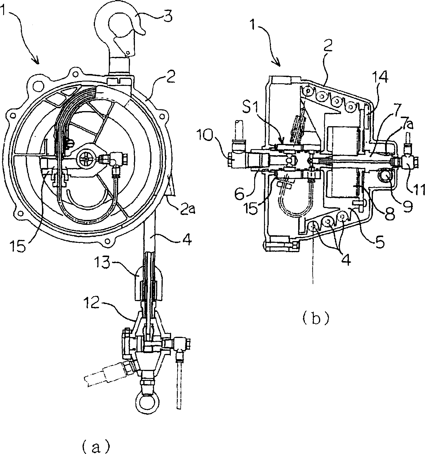
[0030] First refer to Figure 5 The overall structure of the spring balancer of the present invention will be described, and then the configuration of each part will be described in detail in order. Figure 5 It is a figure which shows the spring balancer system (usage example of the spring balancer of this invention) of this invention.

[0031] exist Figure 5 In this case, the spring balancer 1 is suspended by the hook 3 from, for example, a guide rail or the like provided on the ceiling of the work site. A pneumatic tool 34 hangs upside down from the coupler 12 . The pneumatic tool 34 is an air pressure tool that uses compressed air as the rotational power and has a mounting torque detection function.

[0032] In addition, the compressed air primary supply unit 10 and the torque detection signal output unit 11 provided at both ends of the spring balancer 1 are respectively connected to a not-shown compressed air supply source and a work management controller.

[0033] H...

no. 2 example

[0085] Image 6 (a) and (b) are cross-sectional views showing a spring balancer according to a second embodiment of the present invention.

[0086] below, in Image 6 In the spring balancer of the present embodiment shown, the same reference numerals are attached to the parts having the same configuration as those of the above-mentioned first embodiment, and repeated description thereof will be omitted, and the characteristic parts will be described in detail.

[0087] In the spring balancer 41 of this embodiment, the primary side supply part 10 of compressed air and the take-out part 11 of a torque detection signal are arrange|positioned in parallel at one end of this spring balancer 41.

[0088] Here, the structure of the rotary connector 42 in the spring balancer 41 of this embodiment is demonstrated. Figure 7 (a) and (b) are enlarged cross-sectional views showing the rotary connector 42 of the spring balancer 41 of this embodiment.

[0089] The support member S2 is com...

no. 3 example

[0107] The spring balancer of each of the above-mentioned embodiments has a structure in which a double tube type hose is wound on a rotary drum. However, the present embodiment is not limited thereto, and it may be a configuration in which an adhesive hose described later is used instead of a double-tube hose and wound around the rotating drum.

[0108] The spring balancer of the third embodiment of the present invention has the Figure 9 The shown adhesive hose 48 is a spring balancer that is wound around the rotating drum 5 .

[0109] Hereinafter, in the spring balancer of the present embodiment, the same reference numerals are attached to the parts having the same configuration as those of the above-mentioned embodiments, and repeated description thereof will be omitted, and the characteristic parts will be described in detail.

[0110] The spring balancer of this embodiment is the same as the above-mentioned first embodiment, and the primary side supply part 10 of compre...


PUM


Abstract

The spring balancer can ensure the operation space and improve operation environment, and is suitable for hanging pneumatic tool with installation torque testing function. The spring balancer includes one hose member with two pieces of hose; one reel for the hoses to be wound on; one bearing member comprising bearing shaft with two inside air passages and cylindrical rotary connector supported by the bearing shaft for rotating with the reel; and torque applying member for applying torque to the reel. The rotary connector has opening and the opening may be connected to these hoses and these air passages.

Description

technical field [0001] The invention relates to a spring balancer, in particular to a suspension spring balancer suitable for an air pressure tool with a mounting torque detection function. Background technique [0002] Conventionally, spring balancers have been used to suspend (suspend and hold) tools, work machines, and the like at work sites where product assembly is performed. In general, the spring balancer uses a rotatable reel that winds a hanging wire for hanging tools or working instruments, etc., and a force (torque in the winding direction) for winding the wire. The spring applied to the reel is built into the casing. [0003] When hanging and holding an air tool using compressed air as a rotational power source by such a spring balancer, the air tool is suspended on a suspension cable, and compressed air is supplied to the air tool from a separately provided coiled hose or the like. Therefore, the coiled hose is in a messy state in the working space, and there ...

Claims


Application Information

Patent Timeline
Patent Type & Authority Applications(China)
IPC IPC(8): B25F5/00
CPCB25H1/0028
Inventor 高桥信一松田义法冈村义则
Owner ENDO IND
Why Eureka
Try Eureka