Installation structure for lining board of fenderboard

A technology for installing structures and fenders, which is applied to the upper structure, upper structure sub-assembly, transportation and packaging, etc., can solve problems such as deformation of fender splash guards, and achieve deformation prevention, precise installation, and firm installation Effect

Inactive Publication Date: 2004-11-03
SUZUKI MOTOR CO LTD
View PDF1 Cites 4 Cited by
  • Summary
  • Abstract
  • Description
  • Claims
  • Application Information

AI Technical Summary

Problems solved by technology

Therefore, if an external force F acts from the outside of the vehicle body in the direction indicated by the arrow, t

Method used


Image

  • Installation structure for lining board of fenderboard
  • Installation structure for lining board of fenderboard
  • Installation structure for lining board of fenderboard

Examples


Embodiment Construction

[0027] The invention will be described below with reference to the embodiments shown in the accompanying drawings.

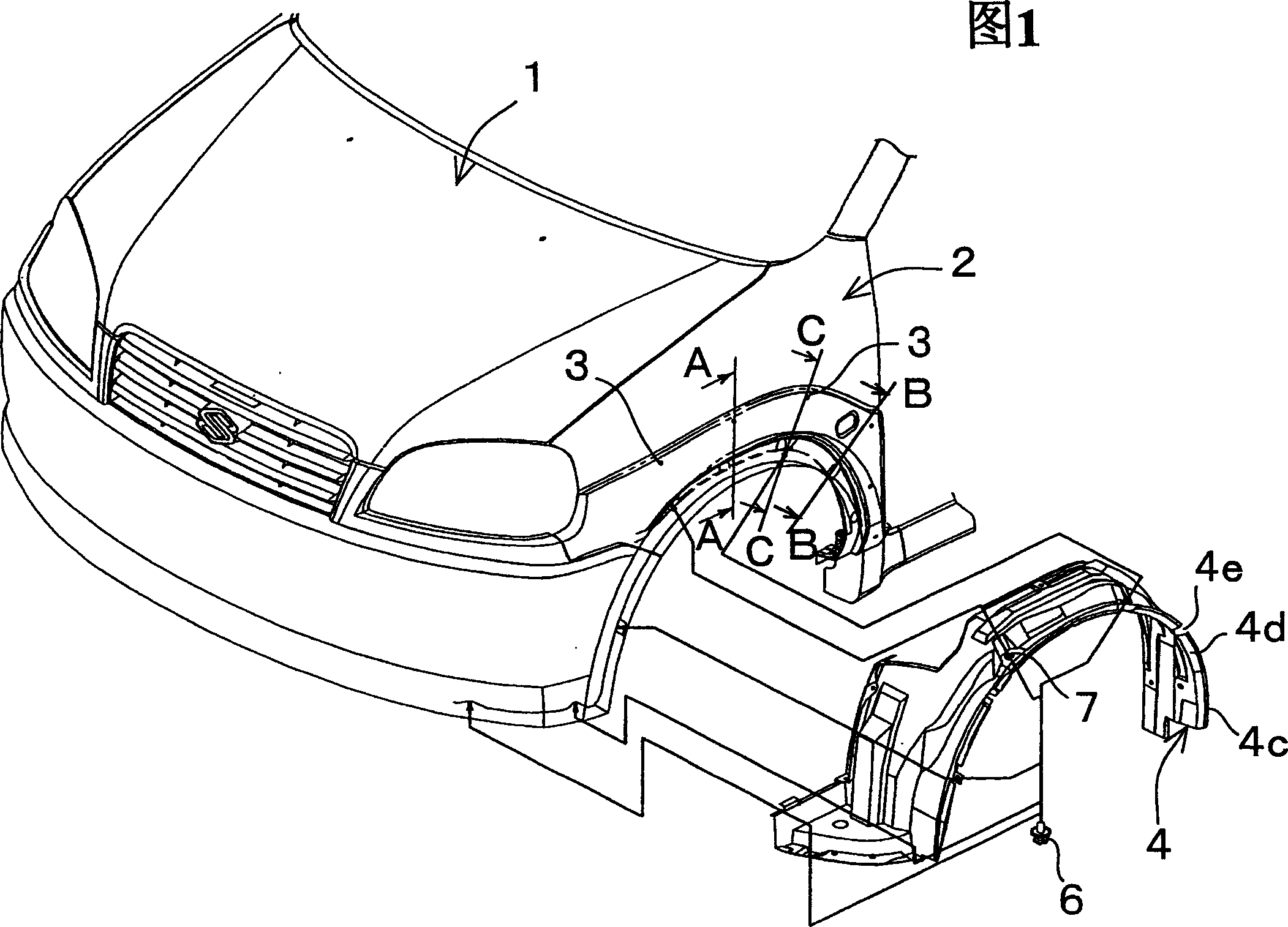
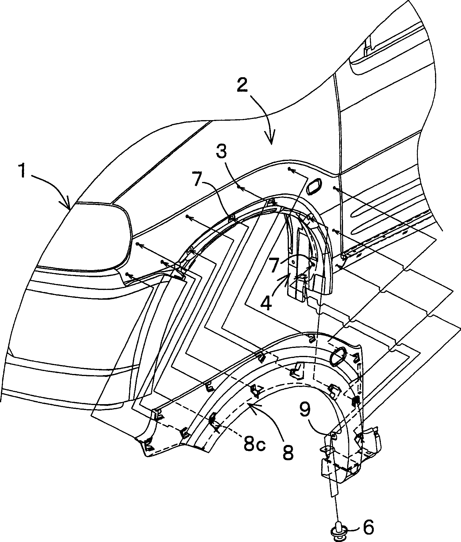
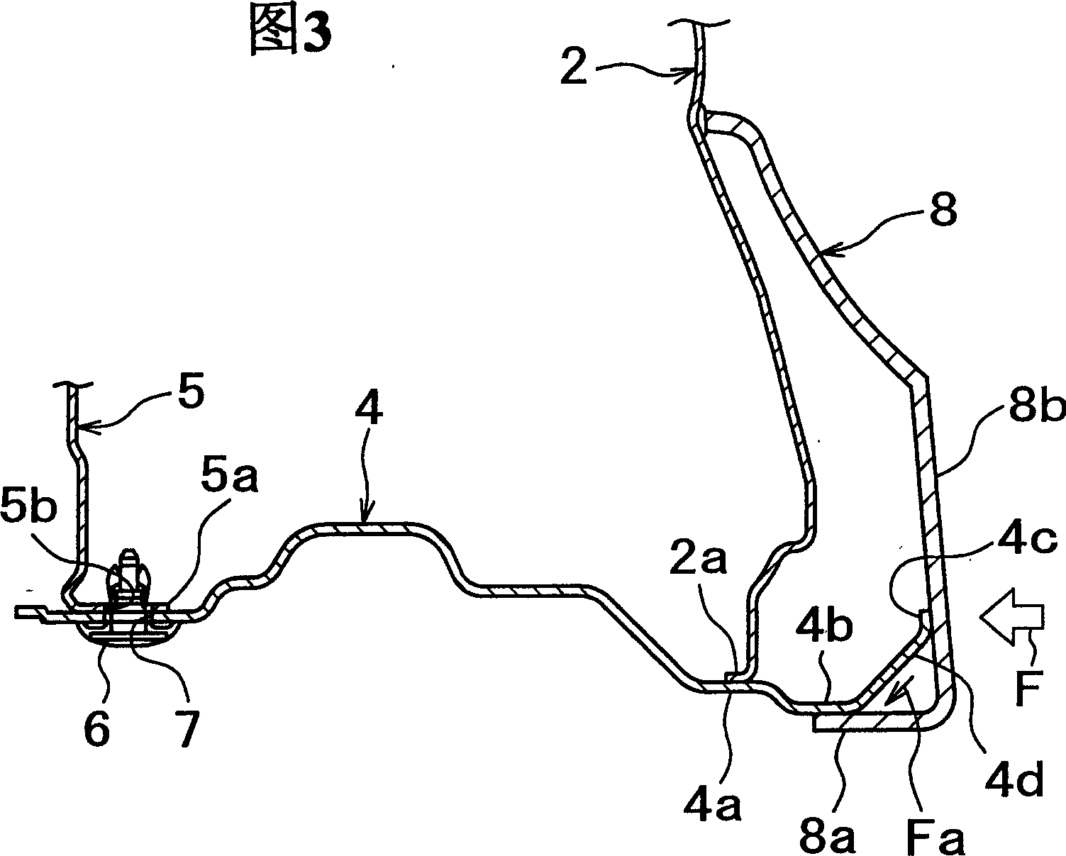
[0028] 1 to 5 show the installation structure of the fender liner according to the present invention. The mounting structure of the present embodiment is used on the left and right sides of the front part of the automobile body, and the front fender 2 is arranged as shown in Fig. 1 and figure 2 shown. At the lower end of this front fender 2, as shown in FIGS. The side surface is formed with a plurality of mounting holes 3 at intervals at predetermined positions. Also, on the inner side of the lower portion of the front fender 2, a front fender liner 4 is provided to surround an upper half (not shown) of a front wheel and prevent mud splashed by the wheel from entering an engine room.

[0029] The front fender liner 4 is an integrally molded product whose entirety is formed in an arc extending longitudinally of the vehicle, is curved upward when viewed from t...


PUM


Abstract

In the mounting structure of the fender lining 4 arranged lower inside of a front fender panel 2, the outside of which is covered with the fender splash guard 8, a second contact surface 4b contacted with the flange 8a of the fender splash guard 8 and a flange 4c extended outward from the second contact surface 4b and contacted with the inner wall surface of the design section 8b of the fender splash guard 8 are provided in the outside of the fender lining 4.

Description

technical field [0001] The invention relates to an installation structure of a fender liner, in particular to an installation structure of a fender liner on a vehicle. Background technique [0002] Generally, on the lower side of the front fender of an automobile, a front fender liner is provided to surround the upper half of the front wheel and prevent mud, etc. splashed by the front wheel from entering the engine room. Various types have been proposed for such a fender liner mounting structure (for example, see Patent Document 1). [0003] Patent Document 1: Japanese Patent Provisional Application Publication No. 11-208514 (No. 208514 / 1999). [0004] For example, in the fender liner installation structure shown in FIGS. 6-8 , the front fender liner 51 is disposed between the front fender 52 and the front side wall 53 in the width direction of the vehicle. Therefore, the mounting portion of the front fender liner 51 has a plurality of clamp holes through which the clamp m...

Claims


Application Information

Patent Timeline
IPC IPC(8): B62D25/18B62D25/16
CPCB62D25/161
Inventor 藤井辰彦
Owner SUZUKI MOTOR CO LTD
Why Eureka
Try Eureka