Light conducting plate structure

A light guide plate and lighting technology, applied in optics, nonlinear optics, diffuser elements, etc., can solve problems such as not being able to meet the light uniformity of surface light sources, and achieve the effect of increasing uniformity

Inactive Publication Date: 2004-11-03
UPEC ELECTRONICS CORP
View PDF5 Cites 14 Cited by
  • Summary
  • Abstract
  • Description
  • Claims
  • Application Information

AI Technical Summary

Problems solved by technology

[0016] However, the simple change of the scattering pattern from small to large or from sparse to dense cannot meet the requirements of light uniformity of surface light sources

Method used


Image

  • Light conducting plate structure
  • Light conducting plate structure
  • Light conducting plate structure

Examples


Embodiment 1

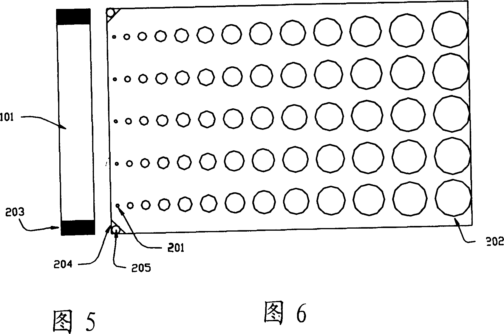
[0054] Embodiment 1 is the concentration distribution of the backlight panel in four seasons. An 84mm×60mm light guide plate is made into a hollow pyramid with a bottom of 40μm×30μm and a height of 5μm. First, according to Table 1, the increment Px in the x direction is selected as a fixed value of 125 μm. The increment Py in the Y direction is based on the parabolic formula Y=A(Y-Yo)^2+B(Y-Yo)+C. Substitute Table 2 A, B, C and Yo into Table 1 Formula 2 Get the Coy value first, and then get the increment Py in the Y direction. After calculation, the starting point coordinates of the first five protrusions in the first row are (0, 0) (0, 0.18) (0, 0.35) (0, 0.53) (0, 0.71). The measured uniformity of luminance of this light guide plate was 81%. The density distribution is shown in Figure 13 and Figure 14.

[0055] The second embodiment is another type of concentration distribution of the four-season backlight. A light guide plate of 84mm×60mm is made into a hollow pyramid ...


PUM

PropertyMeasurementUnit
refractive indexaaaaaaaaaa

Abstract

The side-lighting light guiding board structure with micro lugs is used in the back light module of LCD or similar object. The micro lugs in the light guiding board has parabolic density distribution, that is, the micro lugs density distribution is dense near light source, gradually rarer and densest in the ultimate far position. The micro lugs are in micron level size and interval. The parabolic design can result in efficient homogeneous area light source.

Description

technical field [0001] The invention relates to a side-illuminated light guide plate structure, especially a light guide plate with a specially designed micro-protrusion pattern with a micron-level size and spacing distributed on it. The density distribution of the micro-protrusion pattern is in a parabolic relationship. To efficiently obtain a uniform surface light source. Background technique [0002] Since the liquid crystal display (LCD) is a non-luminous device, the display function needs to be achieved by means of a backlight module. A backlight module generally refers to a component that can provide a surface light source, and can basically be regarded as three parts: a light source, a light guide plate, and an optical film. Among them, the function of the light guide panel (Light Guide Panel or LGP) is to guide the scattering direction of the light to improve the luminance of the panel and ensure the uniformity of the luminance of the panel. The backlight module ha...

Claims


Application Information

Patent Timeline
Patent Type & Authority Applications(China)
IPC IPC(8): G02B5/02G02F1/13357
Inventor 陈元杰陈春夏廖秋峰许生骏
Owner UPEC ELECTRONICS CORP
Why Eureka
Try Eureka