Staple detection mechanism of electric stapler

A detection mechanism and technology for staples, applied in staple tools, staple staple tools, manufacturing tools, etc., can solve problems such as reduced reliability, damage, and obstruction of staple cassette insertion and extraction operations, etc.

Inactive Publication Date: 2004-11-03
MAX CO LTD
View PDF1 Cites 4 Cited by
  • Summary
  • Abstract
  • Description
  • Claims
  • Application Information

AI Technical Summary

Problems solved by technology

For example, the actuation of the switch will operate when the staple row is warped even though there are enough staples remaining in the staple cartridge
Therefore, the reliability of detection has to be reduced
In addition, when the switch is arranged at the above-mentioned channel, if the driver protrudes at a right angle in the channel, the insertion and extraction of the staple cassette will be hindered. Therefore, a mechanism for preventing protrusion at the time of insertion is required, and the installation becomes more difficult.
In addition, when the sensor is arranged near the inlet of the staple cassette, the staple cassette should be inclined relative to the passage when inserting and pulling out, so that the staple cassette and the driver are caught when the cassette is inserted and pulled out. , both are at risk of breakage, so the drive must be strenuously avoided
[0004] Like this, it is very difficult to be arranged on the stapler main body that only has narrow space with common switch

Method used


Image

  • Staple detection mechanism of electric stapler
  • Staple detection mechanism of electric stapler
  • Staple detection mechanism of electric stapler

Examples


Embodiment Construction

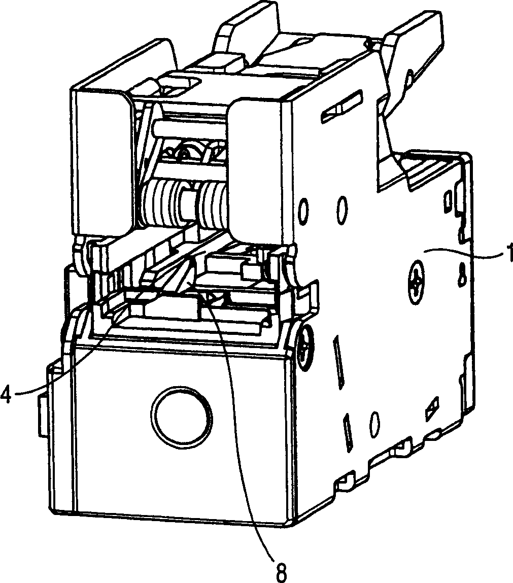
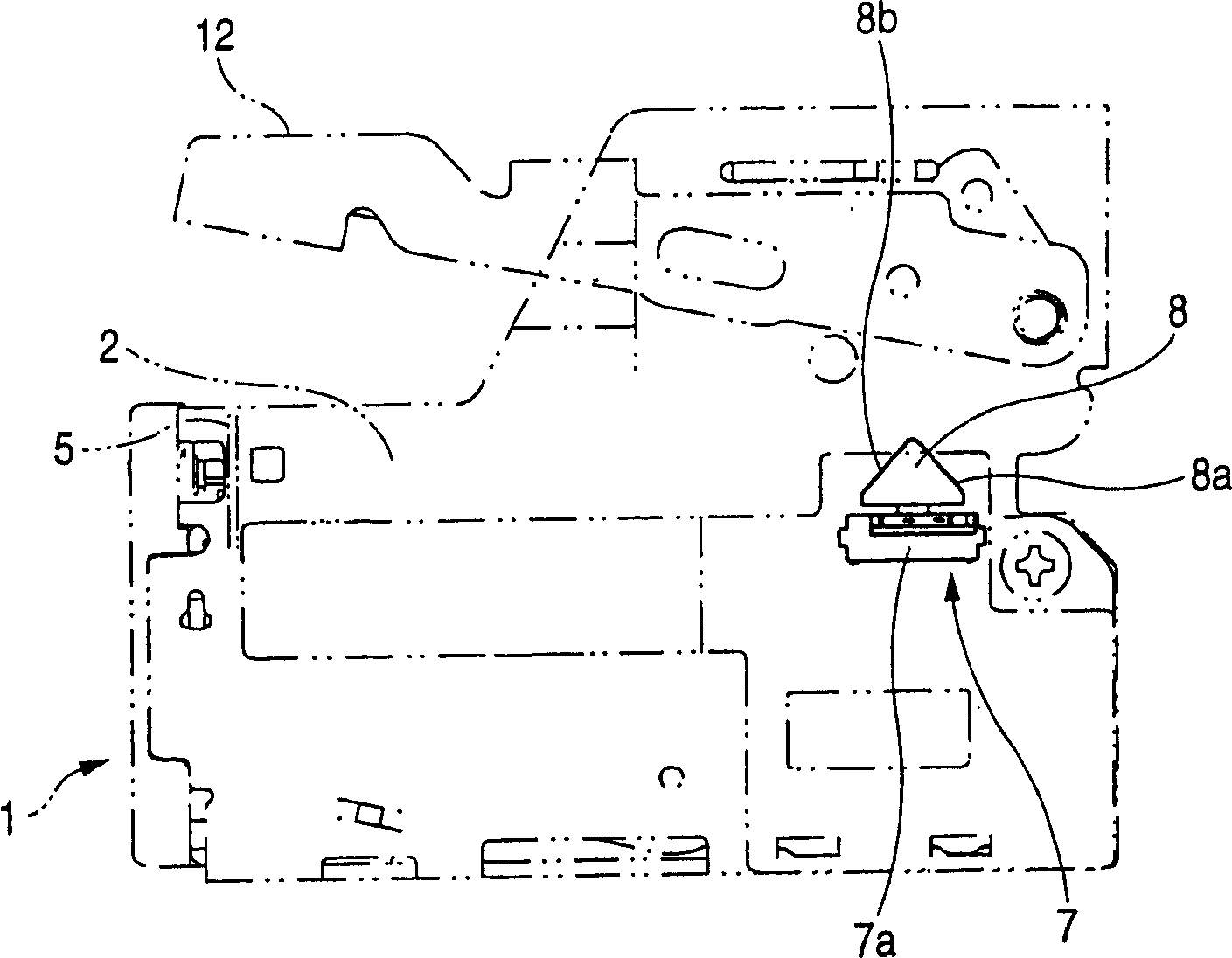
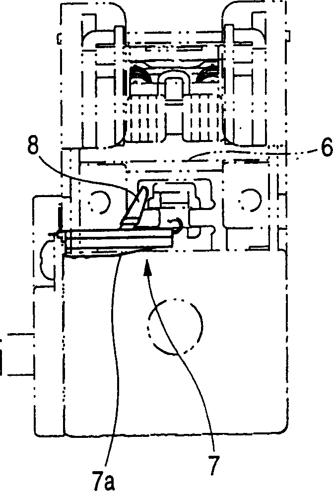
[0017] figure 1 It is a perspective view of the stapler main body of the electric stapler, figure 2 is a schematic diagram of its side, image 3 is the rear view.

[0018] The above-mentioned electric stapler is installed in the feeding part 2 of the stapler main body 1 so that it can be inserted and pulled out freely. Figure 4 and Figure 5 The staple cassette 3 shown, as Figure 6 As shown, in the staple cassette 3, the staple row a (refer to Figure 6 ). In addition, a passage 4 for installing a cassette is formed in the feeder 2 of the stapler main body 1 . And, insert and install the staple cassette 3 in the passage 4, drive the drive plate 5 provided on the stapler main body 1 upwards after the installation, and make the staple at the front end of the staple row a penetrate the bound material (paper) ), and drive the upper arm 12 downwards to bend both sides of the penetrating staple. Delivers the staple row in preparation for the next staple. Next, repeat thi...


PUM


Abstract

In an electric stapler which includes: a passage (4) formed in a magazine portion (2) of the stapler body (1), for attaching and detaching a staple cartridge (3); and sheet staples (a) accommodated in the staple cartridge (3), wherein both side portions of the lead staple (a1) and the following staples of the sheet staples (a) are successively bent and stricken, a staple detection sensor (7), both sides of the end of the actuator (8) of are tapered, is arranged so that both side portions can be directed to an entrance of the passage (4) and the end of the staple detection sensor (7) can be engaged with an upper or a lower face of the sheet staples (a) of the staple cartridge (3) attached into the passage (4). The actuator (8) is swung and tilted in the perpendicular direction to the longitudinal direction of the passage (4) and biased by a spring so that it can obliquely rise at all times.

Description

technical field [0001] The present invention relates to a staple detection mechanism for detecting the presence or absence of staples stored in a staple cassette in an electric stapler. Background technique [0002] Generally, known electric staplers store a staple row in a staple cassette that is connected into sheets by a plurality of linear (flat) staples, and the staple cassette can be inserted or pulled out. In the channel for installing the cassette formed on the feeding part of the main body of the electric stapler, after inserting the staple cassette and installing it, bend both sides sequentially from the staple at the front of the staple row and press out . In the electric stapler of this type, when the remaining amount of staples in the staple cassette is very small, the cassette must be pulled out from the feeder and replaced with a new one. For this reason, it is necessary to provide a staple detection sensor that detects the remaining amount of the staple row...

Claims


Application Information

Patent Timeline
Patent Type & Authority Applications(China)
IPC IPC(8): B27F7/19B25C5/04B25C5/15B25C5/16B27F7/21B27F7/38
CPCB25C5/1689B27F7/38B25C5/16
Inventor 樋口一雄箱崎克也
Owner MAX CO LTD
Why Eureka
Try Eureka