
Air-filling water dash apparatus

A technology of a water blocking device and an inflatable device, which is applied in the direction of rain/wind shields, etc., can solve the problems of heavy sandbags, difficult access to sand and soil, and environmental pollution.

Inactive Publication Date: 2004-11-24
TPO DISPLAY
View PDF0 Cites 23 Cited by
  • Summary
  • Abstract
  • Description
  • Claims
  • Application Information

AI Technical Summary

Problems solved by technology

[0004] 1. Before the flood, every second counts, and the sand in the sandbags is usually not easy to obtain, and the production of sandbags is quite time-consuming, so it is impossible to supply a sufficient number of sandbags in real time, and it is impossible to effectively prevent blockage in a short period of time.
[0005] 2. Since each sandbag is quite heavy, it is obvious that when arranging the sandbags for anti-blocking work, a lot of manpower is required, and even mechanical operations must be performed, so it is a waste of manpower and financial resources
[0007] 4. After the flood recedes, it is necessary to face time-consuming and labor-intensive cleaning problems, and if the sand in the sandbags is dumped arbitrarily, it will pollute the environment

Method used


Image

  • Air-filling water dash apparatus
  • Air-filling water dash apparatus
  • Air-filling water dash apparatus

Examples


Embodiment Construction

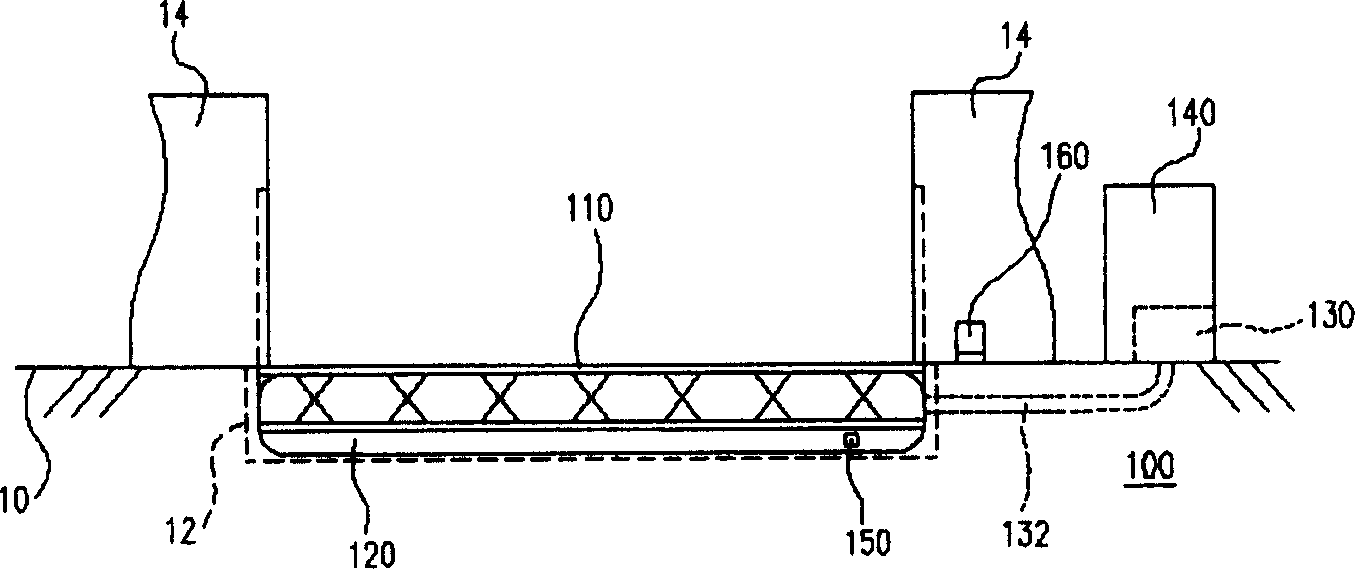
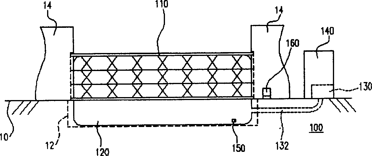
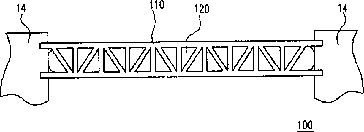
[0018] figure 1 It is a schematic diagram of an inflatable water retaining device accommodated in a groove on the ground according to a preferred embodiment of the present invention, and figure 2 It is a schematic diagram of an inflatable water retaining device connected between two supports according to a preferred embodiment of the present invention. Please refer to figure 1 and figure 2 , the inflatable water retaining device 100 is mainly composed of a guardrail 110 , an airbag 120 , an inflatable device 130 and a control device 140 . Wherein, the guardrail 110 is an elevating guardrail, which can be accommodated in the groove 14 of the ground 12 when not in use on weekdays. Conversely, when in use, both sides of the guardrail 110 can be controlled by the control device 141 to move upward along the sidewalls of the two supports 10 , so that the guardrail 110 can be connected between the two supports 10 . In addition, the above-mentioned guardrail 110 is a grid-shaped...


PUM


Abstract

The present invention provides one kind of inflated water retainer, which is suitable for being installed between two supports. The inflated water retainer consists of protecting rail connected between two supports, air bag configured inside the protecting rail and closed to the supports, inflator connected to the air bag, and controller connected to the protecting rail and inflator electrically so as to control the lifting of the protecting rail and the inflation and deflation of the inflator. The said structure can complete water retaining action fast and occupies less space while being idle.

Description

technical field [0001] The invention relates to a water retaining device, in particular to an inflatable water retaining device. Background technique [0002] Whenever the mildew rain season or typhoon season comes, the abundant rainfall in a short period of time usually far exceeds the discharge flow of the drainage equipment, which makes the drainage equipment unloaded and unable to drain water in real time, causing reports of flooding in various places. situation. The first to bear the brunt is the low-lying areas, such as the basement of the building or the underground parking lot of the factory. Although iron rolling doors, aluminum doors... and other facilities are installed in these places to prevent the random entry and exit of improper personnel, these facilities often have gaps and Can not effectively prevent the phenomenon of water seepage. Therefore, although various doors are installed, in order to prevent flooding, people still choose to pile sandbags to furt...

Claims


Application Information

Patent Timeline
IPC IPC(8): E06B7/26
Inventor 何建民
Owner TPO DISPLAY
Learn More