Safety switch trip linking structure

A technology of safety switches and switches, applied in the direction of electric switches, electrical components, circuits, etc., can solve the problems of slow response of linkage strokes, complicated components, high production costs, etc.

Inactive Publication Date: 2004-11-24
游聪谋
View PDF1 Cites 7 Cited by
  • Summary
  • Abstract
  • Description
  • Claims
  • Application Information

AI Technical Summary

Problems solved by technology

[0008] The purpose of the present invention is to solve the shortcomings of the known switch interlocking structure, such as complicated components, high manufacturing cost, indirect interlocking relationship, slow response of interlocking stroke, and many faults in the operation of the switch, especially

Method used


Image

  • Safety switch trip linking structure
  • Safety switch trip linking structure
  • Safety switch trip linking structure

Examples


Embodiment Construction

[0063] In order to describe the purpose, features and effects of the present invention in detail, through the following preferred embodiments, in conjunction with the accompanying drawings, the present invention will be described in detail:

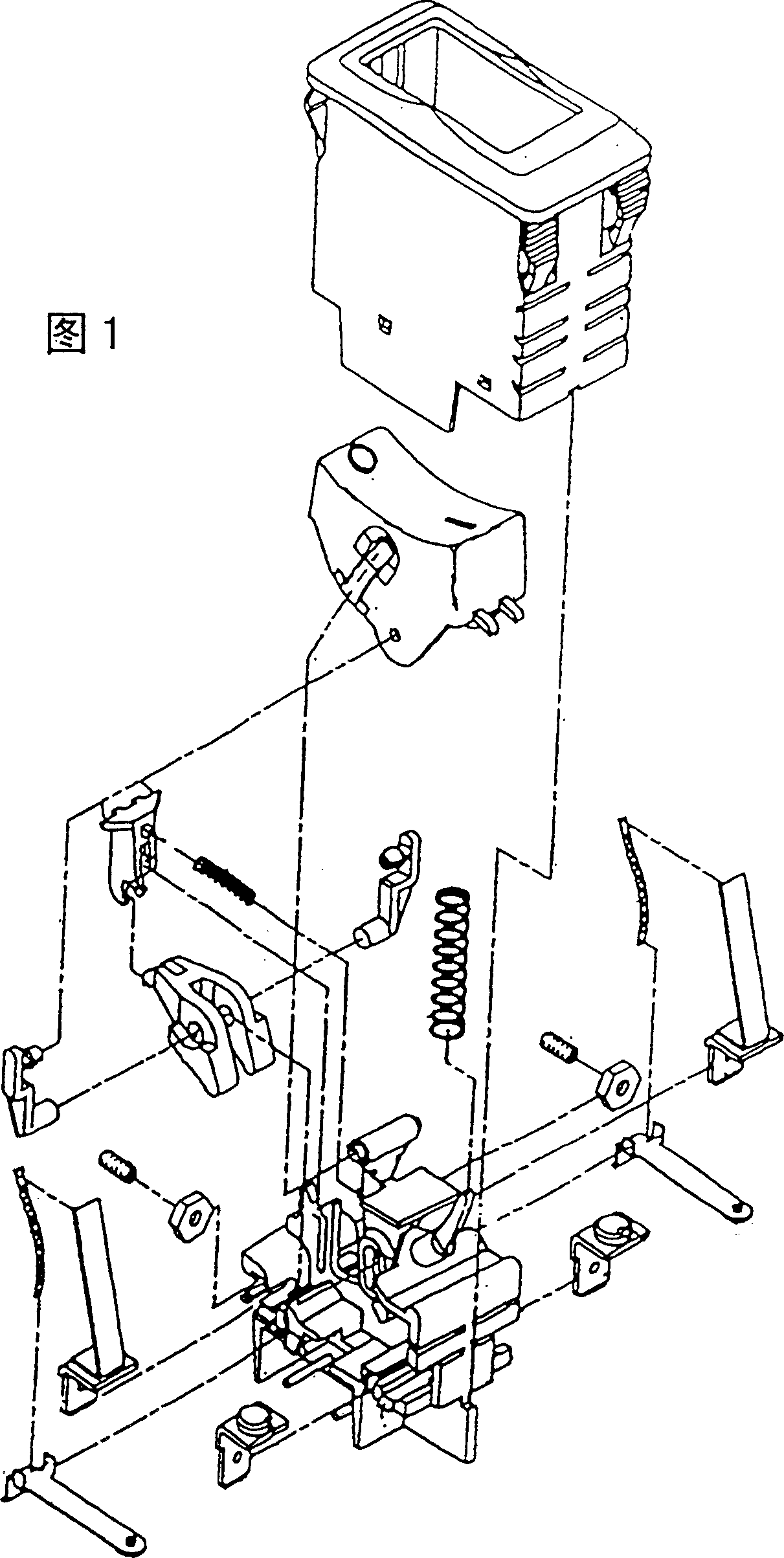
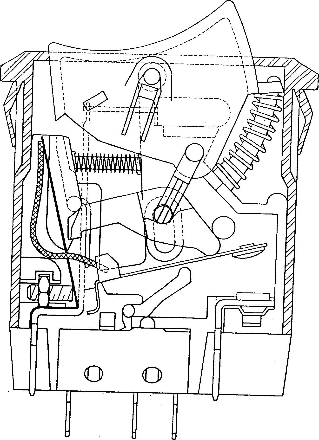
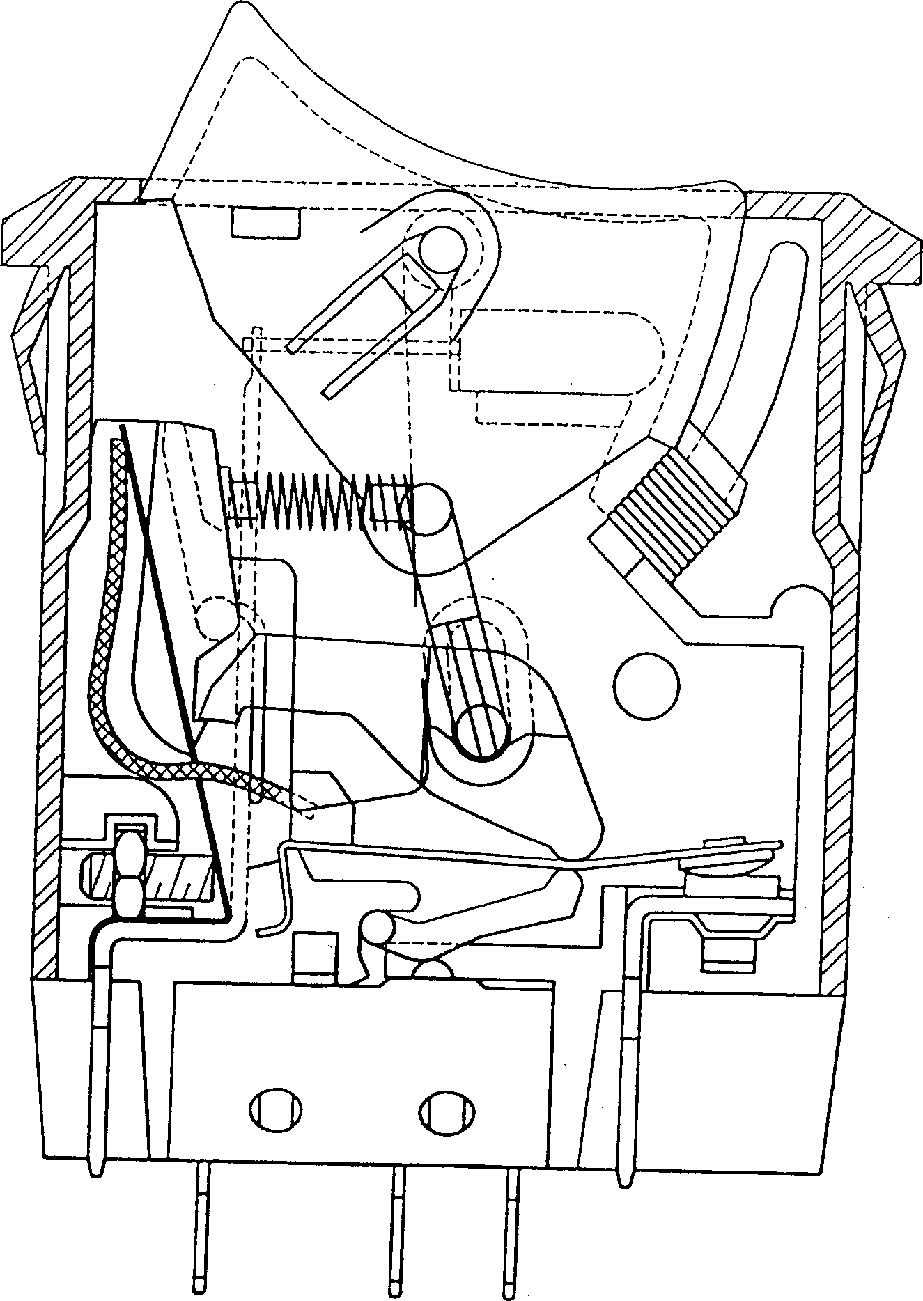
[0064] As shown in Figures 4 to 6, it is an exploded perspective view, a three-dimensional view of the switch body, and a combined sectional view of the embodiment of the present invention; a safety switch tripping linkage structure of the present invention mainly includes a button 1, a switch body 2, A positioning linkage piece 3, a contact piece 4; wherein,

[0065] A cover 10 is combined above the button 1, and at least one clasp 11 protrudes from the side of the button 1. The button 1 is movably embedded in the upper opening of the switch body 2, and at least one elastic member 12 is combined between the button 1 and the switch body 2. , in this embodiment, it is a compression spring, so that the button 1 has an outward and upward ela...


PUM


Abstract

The present invention relates to a safety switch tripping coupled structure. It is characterized by that said invention utilizes the key-pressing operation to couple positioning bar and implement synchronous action, and the mutual coupling action between the positioning bar, ring gradient path and positioning coupling piece can be formed into a cyclic positioning relationship, and the positioning coupling piece can be used to directly push and pull the contact piece to form the switch power-on or power-off. When the current is overloaded under the condition of power-on, the backward bending bounce of the heated and deformed contact piece is said conducting circuit can be used to make the circuit be powered off.

Description

technical field [0001] The invention relates to a safety switch jumping linkage structure, which is a synchronous action of a positioning rod by pressing a button, so that the positioning rod, the ring-shaped staircase and the positioning linkage piece are interlinked to form a circular positioning relationship, and then the positioning The connecting piece directly drives the contact piece to jump, forming the switch to be energized ON or power-off OFF; wherein, the present invention utilizes a plurality of fork-shaped centrally connected grooves in the slot of the positioning connecting piece, and the positioning rod is obtained from this Sliding action in the multiple grooves of the slot, so that the positioning rod is linked to the positioning linkage piece to directly push and pull the contact piece to form a switch that is powered ON or powered off; During the action process from power OFF to power ON, the contact piece will be quickly deformed by heat and reversely bent...

Claims


Application Information

Patent Timeline
IPC IPC(8): H01H13/20
Inventor 游聪谋
Owner 游聪谋
Why Eureka
Try Eureka