Pneumatic tire

A technology of pneumatic tires and tires, which is applied to the reinforcement layer of pneumatic tires, special tires, tire parts, etc., and can solve the problems of low stiffness of bead parts

Inactive Publication Date: 2004-12-01
SUMITOMO RUBBER IND LTD
View PDF1 Cites 17 Cited by
  • Summary
  • Abstract
  • Description
  • Claims
  • Application Information

AI Technical Summary

Problems solved by technology

[0004] However, in such an elongated bead structure, since the rigidity of the bead portion is relatively low, the protrusion of the sidewall portion increases due to tire inflation.

Method used


Image

  • Pneumatic tire
  • Pneumatic tire
  • Pneumatic tire

Examples


no. 1 example

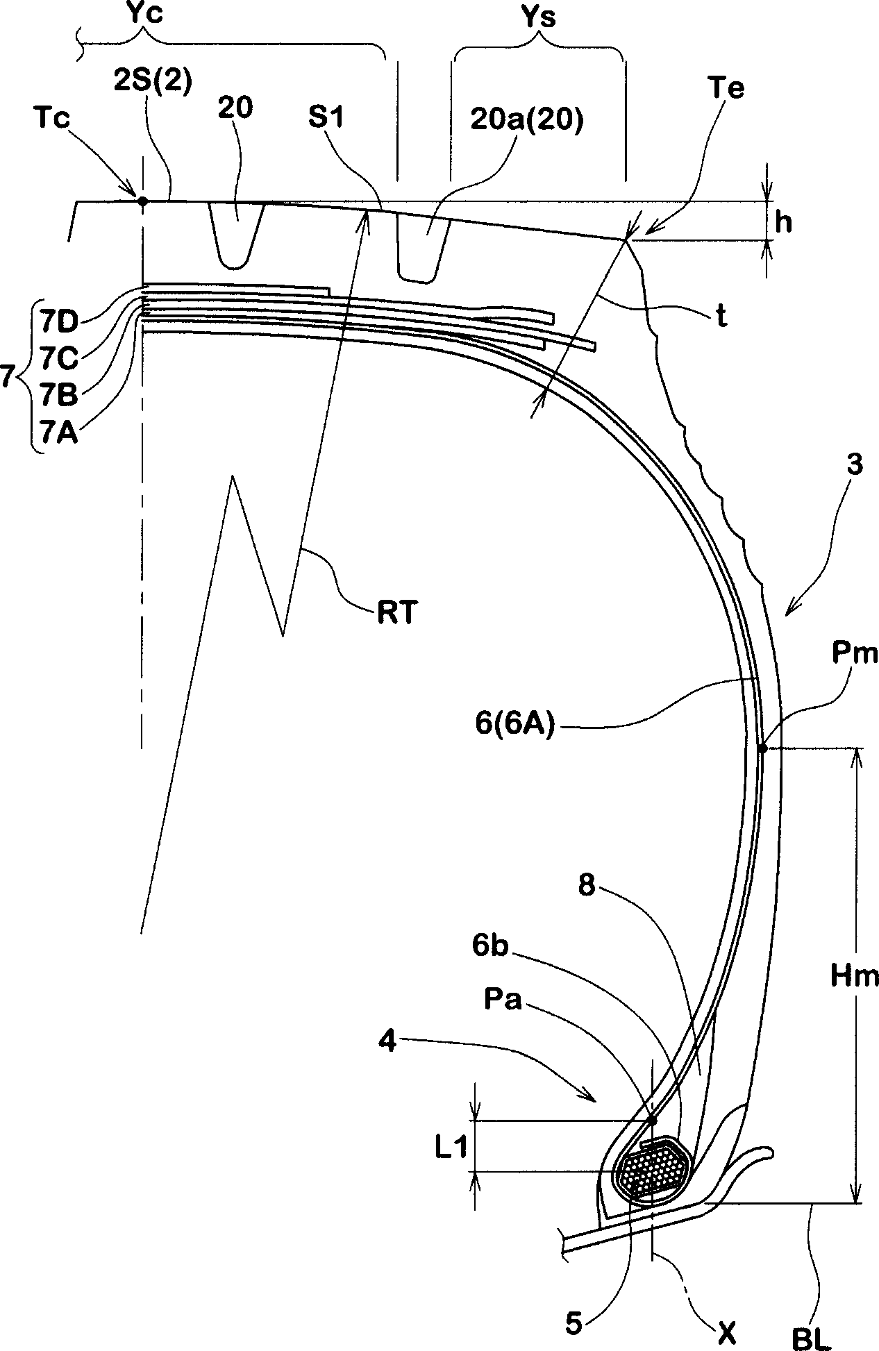
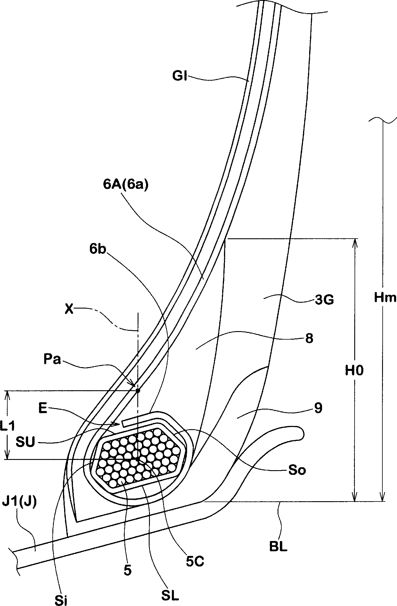
[0034] figure 1 and figure 2 Shown is a first embodiment in which the carcass ply edge is positioned adjacent to the radially outer side SU of the bead core 5 . The wrapping portion 6b of the carcass 6 extends axially inwardly along the radially outer surface SU and terminates before the carcass body portion 6a, leaving a space Lb between its end point E and the body portion 6a.

[0035] The bead top rubber 8 is placed radially outside the winding portion 6 b to secure its end point E between the bead core 5 and the bead top rubber 8 . The bead apex rubber 8 is made of hard rubber having a JIS Type A durometer hardness ranging from 60 to 99, and extends from the bead core 5 to a lower portion of a sidewall while radially outward Tapers until its radially outer ends form a triangular section. In terms of bead rigidity and weight reduction, the radial height H0 of the bead apex rubber 8 from the bead base line BL is preferably set at 30% of the radial height Hm of the maxim...

no. 2 example

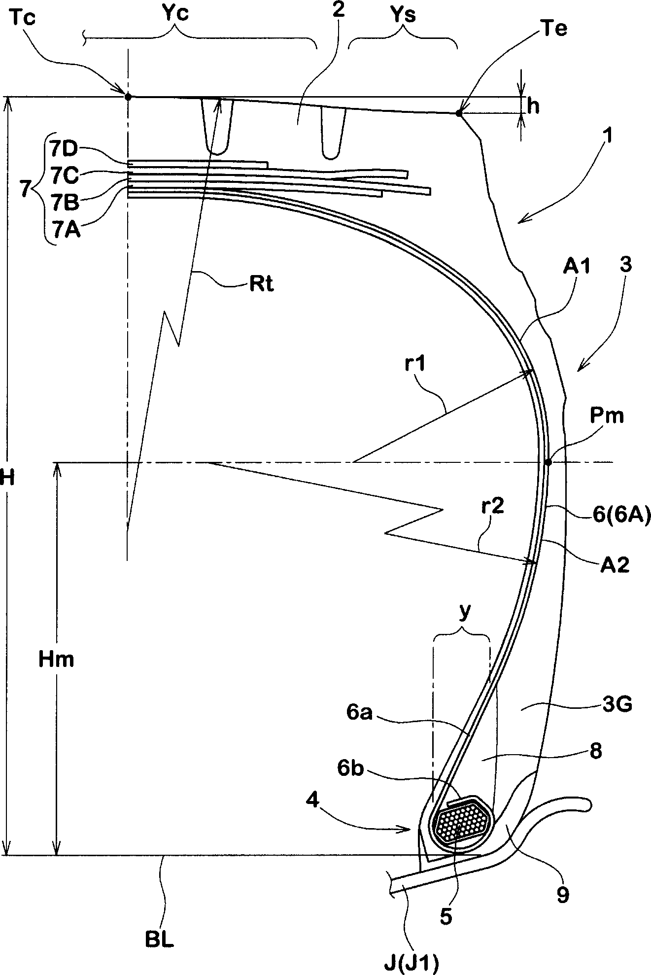
[0055] image 3 and Figure 4 A second embodiment is shown. This embodiment is similar to the first embodiment. Therefore, only the points of difference between them will be described. Refer to the first embodiment for the unexplained content.

[0056] In this embodiment, the carcass profile differs in that the carcass body portion 6a in the sidewall portion 3 comprises:

[0057] an intermediate outer portion A1 extending radially outwardly from a point of maximum cross-sectional width Pm at a tire section height H greater than the bead bottom line BL, having a radius of curvature r1 50% of the radial height h1;

[0058] an intermediate inner portion A2 extending radially inwardly from said point Pm, having a radius of curvature r2 greater than said radius r1, preferably in the range of 1.5 to 2.0 times radius r1 ( image 3 The example is about 1.75 times).

[0059] A substantially straight portion 6a1 in the aforementioned core zone (y) with a relative axial position b...

no. 3 example

[0075] Figure 5 and Figure 6 Shown is a third embodiment. This embodiment is similar to the second embodiment except for the features described below. Therefore, reference is made to the first and second embodiments for matters not explained.

[0076] If the carcass cord is thick and the recoil of the wrap is strong, voids are likely to be formed between the wrap and the bead core when the green tire is processed, and the incidence of molding defects increases. In this case, it is better to use this structure.

[0077] In this embodiment, the carcass layer 6A is not completely wrapped around the bead core as in the previous two embodiments.


PUM


Abstract

A pneumatic tire comprises a tread portion (2) with tread edges (Te), a pair of sidewall portions (3), a pair of bead portions (4) each with a bead core (5) therein, and a carcass ply (6) of cords comprising a main portion (6a) extending between the bead cores through the tread portion and sidewall portions and a wound portion (6b) wound around the bead core (5) in each said bead portion (4) from the inside to the outside of the tire, and an edge (E) of the wound portion (6b) is disposed between the bead core (5) and a bead apex rubber (8) disposed radially outside the bead core (5) to be secured therebetween.

Description

technical field [0001] The present invention relates to a pneumatic tire, and more particularly, to a bead structure of a pneumatic tire suitable for a heavy-duty tire, which can reduce the volume and weight of the bead portion. Background technique [0002] Generally, in order to be able to withstand severe usage conditions such as heavy loads and high inflation pressures, pneumatic tires for heavy-duty usage such as truck / bus tires have large bead portions such as Figure 7 shown. [0003] In recent years, on the other hand, in order to reduce tire weight, so-called elongated bead structures have been proposed in laid-open Japanese patent application JP-A-H9-11715 (corresponding to US Pat. No. 5,772,811), such as Figure 8 shown. [0004] However, in such an elongated bead structure, since the rigidity of the bead portion is relatively low, the protrusion of the sidewall portion increases due to inflation of the tire. Thus, the shoulders are stretched radially inward. T...

Claims


Application Information

Patent Timeline
Patent Type & Authority Applications(China)
IPC IPC(8): B60C3/04B60C11/00B60C15/00B60C15/06
CPCB60C3/04B60C2011/013B60C11/00B60C11/0083B60C15/06B60C9/0292B60C15/0027B60C2015/044Y10T152/10819Y10T152/10828Y10T152/10846Y10T152/10855
Inventor 丸冈清人西实山平笃
Owner SUMITOMO RUBBER IND LTD
Why Eureka
Try Eureka