
Eureka
For R&D, Eureka makes reading and utilizing patents & technical documents easy.
Eureka AIR
Designed for self-driven R&D workflows. Generate viable solutions, solve complex R&D challenges, empower your innovation with AI.

Eureka Materials
Designed for material experts only. Revolutionize your material R&D, from search, analyze, to developing new materials.

TechResearch
Generate reliable direction feasibility study reports for your R&D in just a few steps.

TechSeek
Discover and master advanced knowledge NOW. Basics, ideas, possibilities, all at once.

TechMind
As an expert in R&D Theories, TechMind can generates customized viable solutions instantly.

TechRisk
Analyze your overall solution with one click, know your potential R&D risks in advance.

TechMonitor
Get weekly tech updates, stay abreast of the latest tech innovations and key insights.
Method of joining ITM materials using a partially- or fully-transient liquid phase
A technology for connecting materials and multi-components, applied in the direction of separation methods, welding/cutting media/materials, chemical instruments and methods, etc.
- Summary
- Abstract
- Description
- Claims
- Application Information
AI Technical Summary
Problems solved by technology
Method used
Image

Examples
Embodiment 1-2
[0073] Example 1-2: La 0.4 Sr 0.6 CoO 3-δ Disc and Tube Connections
[0074] The joint material batches shown in Table 1 were prepared by brushing and shaking the material in a 250 ml polyethylene tank for 1 hour with 100 g of 2-propanol and 250 g of spherical Y-TZP media. The slurry was dried and then dry milled for 30 minutes before being screened through a 20 mesh screen. The powder was calcined by heating at 100°C / hour to 900°C for 10 hours before cooling to room temperature at 100°C / hour. The calcined powder was sieved through a 40 mesh screen using an alumina pestle before preparing a slip by adding 0.5 g of polyvinyl butyral (PVB) as a dispersant to 38.0 g of toluene and 9.5 g of ethanol. 100 grams of calcined powder was added to a 250 ml polyethylene jar along with 250 grams of Y-TZP medium. The slip was placed on a brush shaker for 1 hour. Binder (7.25 grams of PVB) and plasticizer (3.88 grams of butyl benzyl phthalate (BBP)) were added so that the slip had a so...
Embodiment 3-10
[0084] Embodiment 3-10: the preparation of ink
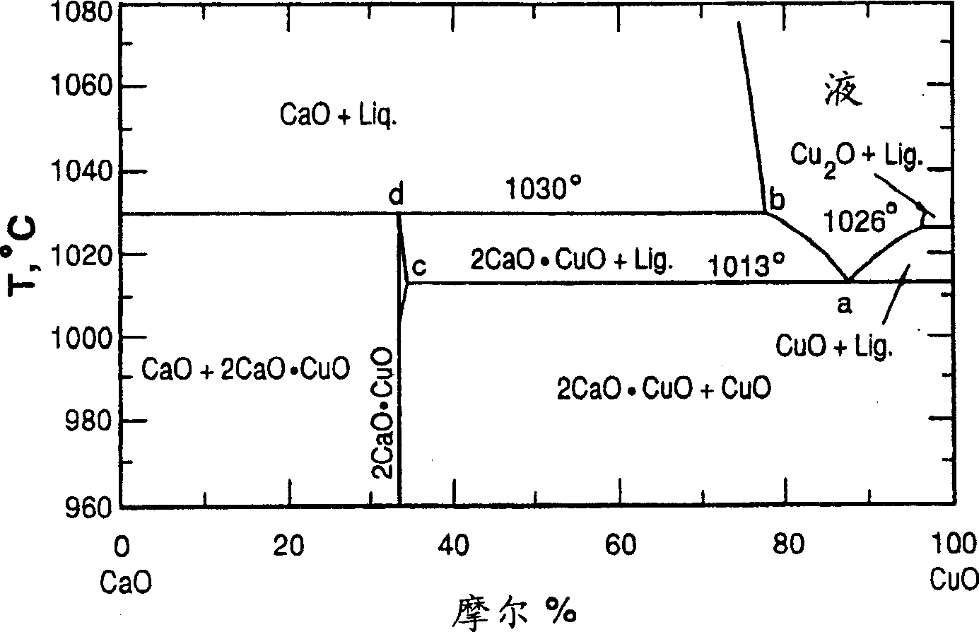
[0085] To illustrate the whole range of compositions, 8 inks were prepared from the compositions shown in Table 2, ie from pure CuO and mixtures of copper oxide and calcium oxide. figure 2 Phase diagrams for Cu and Ca in air are shown, indicating that all components should have some proportion of molten phase above 1026°C. Example 5, the eutectic composition will form a liquid at the lowest temperature, and Example 10 will have the least amount of liquid phase at all temperatures.
[0086] Table 2
[0087] Composition number
Element
mass (g)
CuO
CaCO 3
3
CuO
200
0.0
4
CuO-0.1CaCO 3
175.5
24.53
5
CuO-0.15CaCO 3
163.7
36.34
6
CuO-0.2CaCO 3
152.1
47.86
7
CuO-0.3CaCO 3
129.9
70.06
8
CuO-0.4CaCO 3 ...
Embodiment 11-15
[0093] Examples 11-15: Connection of components
[0094] Ink 3-10 from Examples 3-10 was distributed onto the tube as in the tube-disc contact, and the tube was then placed on the disc and turned to squeeze the ink out, thereby displacing the milled La 0.4 Sr 0.6 CoO 3-δ (LSCo) tubing was attached to the milled LSCo disc. The ink is dried with warm moving air.
[0095] 18 tubes were connected to 18 discs at a pressure of about 10 kPa by heating at 1250°C for 1 hour using the following heating / cooling profile: from room temperature (RT) to 1250°C (at 1250°C 1 hour), at 50°C / hour from 1250-700°C, at 25°C / hour from 700-650°C, at 17°C / hour from 650-600°C, at 10°C / hour from 600-550°C, to 5°C / hour from 550-500°C, 2.5°C / hour from 500-450°C, 2°C / hour from 450-400°C, 50°C / hour from 400-20°C. After sealing the tubes are checked for leaks. Selected specimens were polished with diamond paste, or crushed, before observation by SEM. The cross-section of the polished tube was checked ...
PUM
| Property | Measurement | Unit |
|---|---|---|
| thickness | aaaaa | aaaaa |
| diameter | aaaaa | aaaaa |
| diameter | aaaaa | aaaaa |
Abstract
Description
Claims
Application Information
 - R&D Engineer
- R&D Manager
- IP Professional
- Industry Leading Data Capabilities
- Powerful AI technology
- Patent DNA Extraction
Browse by: Latest US Patents, China's latest patents, Technical Efficacy Thesaurus, Application Domain, Technology Topic, Popular Technical Reports.
© 2024 PatSnap. All rights reserved.Legal|Privacy policy|Modern Slavery Act Transparency Statement|Sitemap|About US| Contact US: help@patsnap.com