Steam generator operating on fossil fuel

A technology of steam generators and fossil fuels, applied in steam generation, steam boilers, steam superheating, etc., can solve problems such as complex systems and a large amount of design workload, and achieve low design and production costs, favorable distribution, and reliable pressure balance Effect

Inactive Publication Date: 2004-12-01
SIEMENS AG
View PDF1 Cites 0 Cited by
  • Summary
  • Abstract
  • Description
  • Claims
  • Application Information

AI Technical Summary

Problems solved by technology

Although this is a simple measure, such a steam generator design for the newly prescribed boundary conditions still requires a relatively large design effort due to the complexity of the underlying system

Method used


Image

  • Steam generator operating on fossil fuel
  • Steam generator operating on fossil fuel
  • Steam generator operating on fossil fuel

Examples


Embodiment Construction

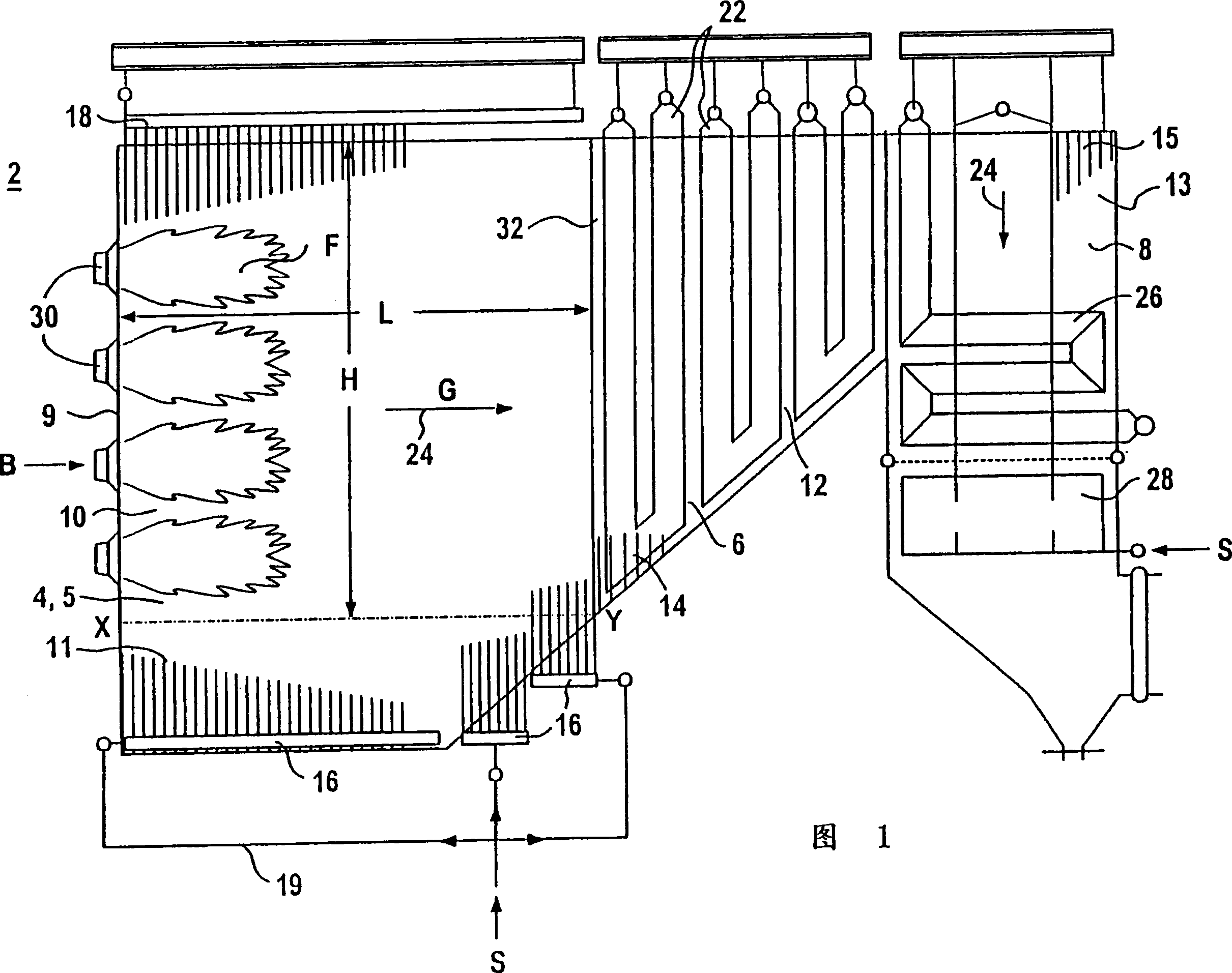
[0042] The steam generator 2 shown in FIG. 1 is assigned to a power plant, not further shown in the figure, which also includes a steam turbine arrangement. The steam produced in the steam generator is used to drive a steam turbine, which in turn drives a generator to generate electricity. The electricity generated by the generator is then fed into an integrated or separate grid. Furthermore, a steam fraction can also be tapped to feed an external process connected to the steam turbine arrangement, which can be a heating process in this case.

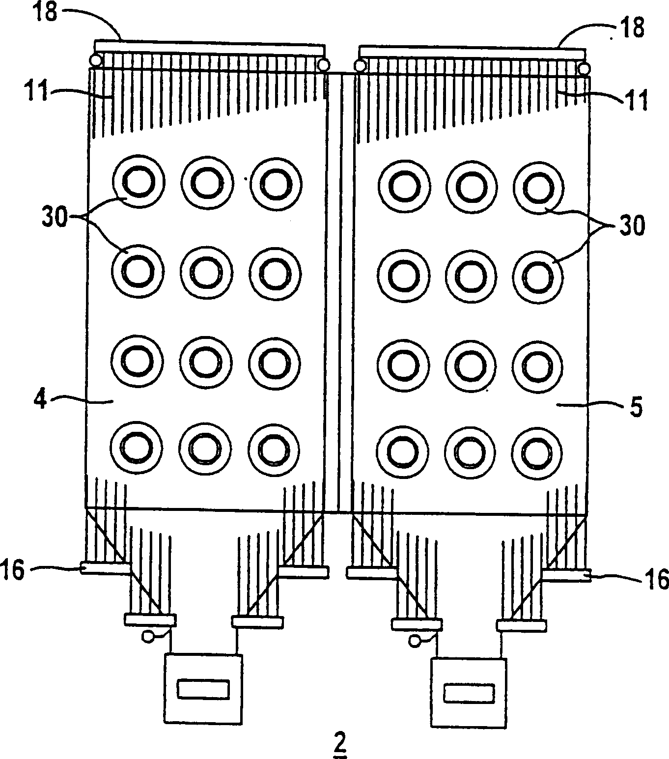
[0043] The steam generator 2 shown in FIG. 1 for heating by burning fossil fuels is advantageously designed as a once-through steam generator. It includes a first horizontal combustion chamber 4 and a second horizontal combustion chamber 5, only one of which can be seen since FIG. 1 shows a side view of the steam generator 2. Downstream of the combustion chambers 4 and 5 of the steam generator 2 in the direction of the hot flue gas fl...


PUM


Abstract

A steam generator has an especially simple structural concept of a combustion chamber for a predetermined output range and for various qualities of different fossil fuels. The steam generator includes a first combustion chamber and a second combustion chamber which have a respective number of burners for fossil fuel and are constructed for an approximately horizontal main flow direction of heating gas. The first combustion chamber and the second combustion chamber open into a common horizontal gas flue connected upstream of a vertical gas flue on the heating-gas side.

Description

[0001] This application is a divisional application of the original application whose filing date is January 10, 2000, application number is 00802873.7, and the invention name is "steam generator for burning fossil fuel". technical field [0002] The present invention relates to a steam generator comprising a first combustion chamber and a second combustion chamber each having fossil fuel burners. Background technique [0003] In power plant equipment equipped with a steam generator, the combustion heat of the fuel is fully utilized to evaporate the flow medium in the steam generator. For evaporating the flow medium, the steam generator has evaporator tubes in it, and the flow medium flowing therein is evaporated by heating these evaporator tubes. The steam produced by the steam generator can be used again, for example, in a connected external process, but also for driving a steam turbine. If the steam drives a steam turbine, the turbine shaft through the steam turbine usua...

Claims


Application Information

Patent Timeline
Patent Type & Authority Applications(China)
IPC IPC(8): F22B21/12F22B21/34F22B31/04F22B37/10F22B37/40F22G7/12
CPCF22B37/40F22B31/04F22B21/346F22B21/34
Inventor 乔基姆·弗兰克鲁道夫·克拉尔
Owner SIEMENS AG
Why Eureka
Try Eureka