Cleaner cartridge

A technology of cleaners and detergents, applied in the direction of cleaning equipment, cleaning machinery, cleaning methods and utensils, which can solve the problems of poor cleaning solution flow control, high volume flow, low efficiency, mixing, etc.

Inactive Publication Date: 2004-12-01
TENNANT COMPANY
View PDF7 Cites 13 Cited by
  • Summary
  • Abstract
  • Description
  • Claims
  • Application Information

AI Technical Summary

Problems solved by technology

[0007] Accordingly, prior art hard floor surface cleaners suffer from several disadvantages that result in an inefficient floor cleaning operation.
Most disadvantages stem from poor cleaning solution flow control and high volume flow of cleaning solution applied to hard floor surfaces
Additional problems can also arise from having to manually prepare cleaning solutions, for example, by mixing too much or too little detergent in the water

Method used


Image

  • Cleaner cartridge
  • Cleaner cartridge
  • Cleaner cartridge

Examples


Embodiment Construction

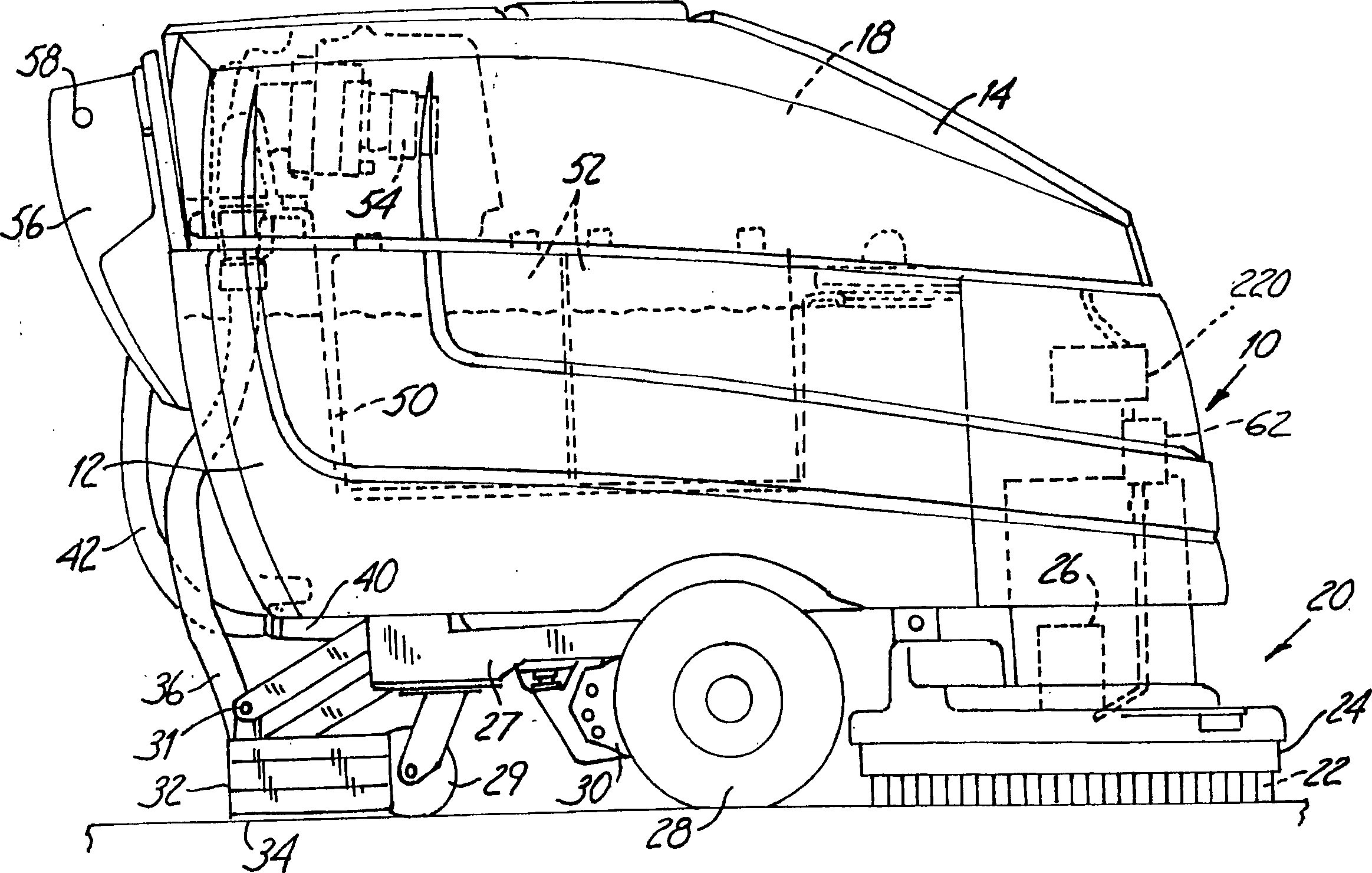
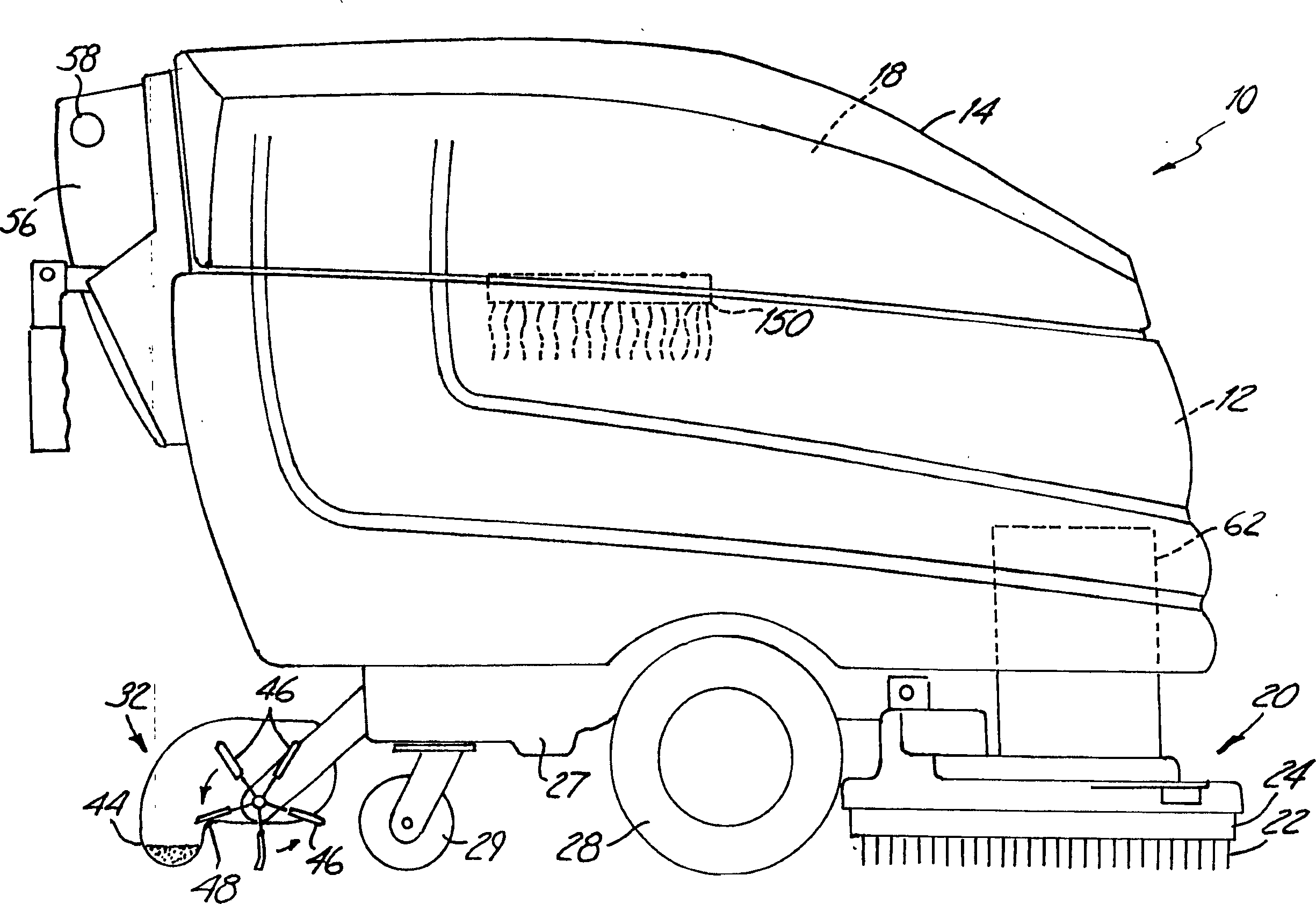
[0022] figure 1 A hard floor surface cleaner 10 is shown in which embodiments of the present invention may be used. The illustrated cleaner 10 is a walk behind cleaner for cleaning hard floor surfaces such as concrete, tile, vinyl, terrazzo and the like. Alternatively, cleaner 10 may be a ride-on or towed-behind cleaner that performs the scrubbing operations described herein. Cleaner 10 includes an electric motor powered by a built-in power source, such as a battery, or by an electrical cable. Alternatively, an internal combustion engine system can be used alone or in combination with an electric motor. Cleaner 10 generally includes a recovery tank 12 , and a cover 14 . The cover 14 is connected along one side of the recovery tank 12 by a hinge (not shown) so that the cover 14 can be turned upward to gain access to the inside of the tank 12 . The cleaner 10 also includes a tank 18 for containing the cleaning liquid or primary cleaning liquid composition that is applied to ...


PUM


Abstract

A cleaner cartridge (150) includes a container (152) having an interior cavity (154), in which cleaning agent can be stored. A first end (158) of conduit (156) is fluidically coupled to the interior cavity. A second end (160) of the conduit is connectable to a chemical dispenser (60).

Description

technical field [0001] The present invention relates generally to hard floor surface cleaners, and more particularly to a cleaner cartridge for a hard floor surface cleaner to contain a supply of detergent for cleaning a liquid distribution system. Background technique [0002] Hard floor surface cleaners are widely used for cleaning floors of industrial and commercial buildings. They range in size from small cleaners controlled by an operator walking behind the cleaner and capable of cleaning paths ranging from 15 inches to 36 inches wide, to those controlled by an operator riding on the machine and capable of cleaning 5 feet wide The path varies between large cleaners. These hard floor surface cleaners include motorized wheels, a solution tank to hold cleaning solution, and a recovery tank to hold dirty cleaning solution recovered from the ground being scrubbed. A cleaning solution, usually comprising a detergent mixed with water, is applied to the hard floor surface adj...

Claims


Application Information

Patent Timeline
Patent Type & Authority Applications(China)
IPC IPC(8): A47L11/03A47L11/16A47L11/18A47L11/29A47L11/30B01F3/04B01J13/00B65D77/06
CPCA47L11/4016A47L11/03B01J13/0095A47L11/4038B01F3/04992A47L11/4011A47L11/4088A47L11/30A47L11/4083A47L11/29B01F23/291B08B3/08
Inventor 布鲁斯·F·菲尔德丹尼尔·L·乔因特杰弗里·A·约翰逊约瑟夫·K·克鲁格布赖恩·L·克里斯坦森
Owner TENNANT COMPANY
Why Eureka
Try Eureka