Time stamp value controller

A technology for controlling device and time, applied in the direction of pulse modulation television signal transmission, simultaneous/sequential multi-television signal transmission, television, etc., can solve the problems of increasing the storage table of time information, reducing the storage efficiency, unable to control the frame rate, etc.

Inactive Publication Date: 2004-12-08
PANASONIC MOBILE COMM +1
View PDF1 Cites 8 Cited by
  • Summary
  • Abstract
  • Description
  • Claims
  • Application Information

AI Technical Summary

Problems solved by technology

[0007] However, in the aforementioned devices that cannot control the frame rate and devices that can only provide representation times with fixed intervals (20 microsecond intervals, etc.) to the generated AV data frames, if the described Multiplexing, the representation time information storage table will increase, resulting...

Method used


Image

  • Time stamp value controller
  • Time stamp value controller
  • Time stamp value controller

Examples


Embodiment 1

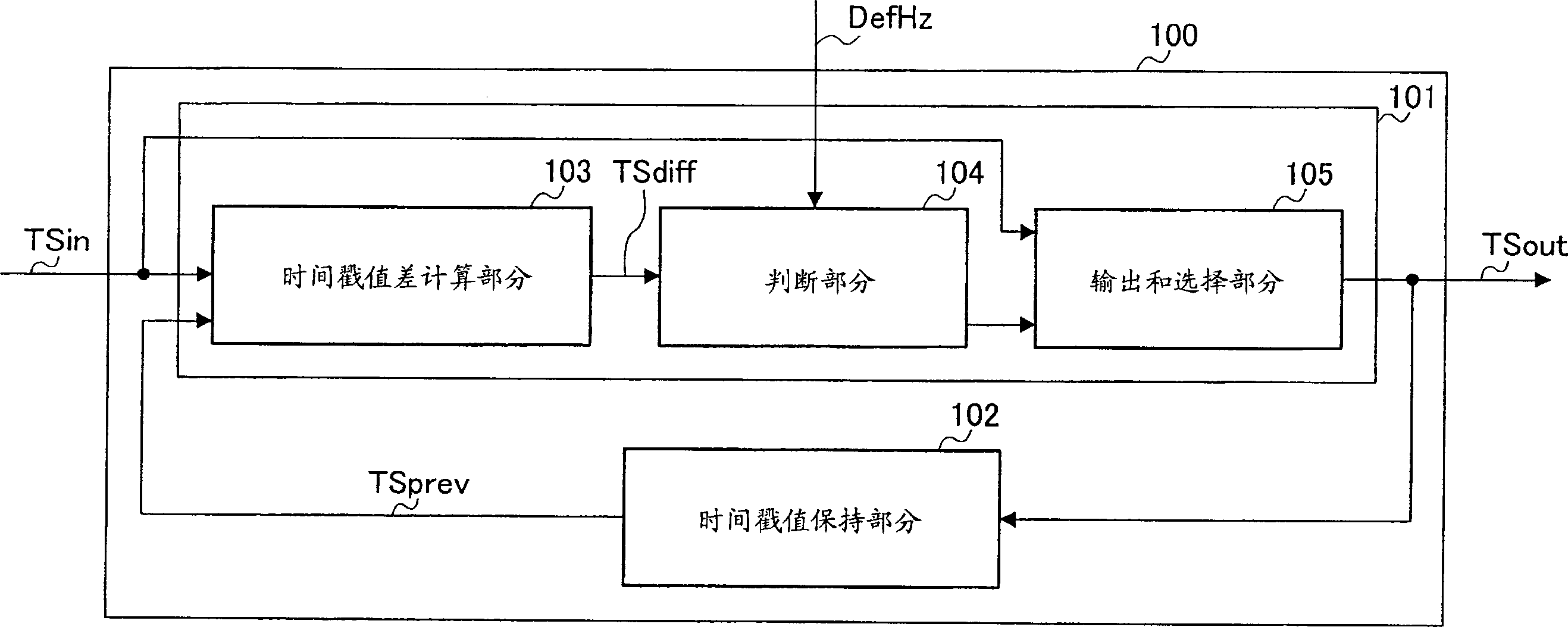
[0020] figure 2 The block diagram of is showing the structure of the time stamp value control device according to Embodiment 1 of the present invention.

[0021] A time stamp value control device 100 according to Embodiment 1 of the present invention includes a time stamp value control section 101 and a time stamp value holding section 102 . The time stamp value control section 101 controls a time stamp value to be added to data on the basis of receiving an input time stamp value TSin and a previous time stamp value TSpref.

[0022] The time stamp value holding section 102 is connected to the time stamp value control section 101 for temporarily holding the slave time stamp value control section as the previous time stamp value TSpref to be supplied to the time stamp value control section 101 101 outputs the output timestamp value TSout. The time stamp value holding section 102 is constituted by, for example, a delay section.

[0023] The time stamp value control section 10...

Embodiment 2

[0037] Embodiment 2 of the present invention will be explained below with reference to the accompanying drawings. Figure 5 The block diagram of is showing the structure of the device for controlling the timestamp value according to Embodiment 2 of the present invention. In Embodiment 2, the same reference numerals as in Embodiment 1 denote the same members as in Embodiment 1.

[0038] The time stamp value control device 400 according to Embodiment 2 of the present invention is by adding a reference frame interval value update part 401 to figure 2 It is formed in the time stamp value control device according to Embodiment 1 of the present invention. The reference frame interval value update section 401 is connected to the time stamp value difference calculation section 103 and the judgment section 104 .

[0039] The reference frame interval value update section 401 receives the time stamp value difference TSdiff, the reference frame interval value DefHz, and the judgment re...

Embodiment 3

[0044] Embodiment 3 of the present invention will be explained below with reference to the accompanying drawings. Image 6 The block diagram of is showing the structure of the time stamp value control device according to Embodiment 3 of the present invention. In Embodiment 3, the same reference numerals as in Embodiment 1 denote the same components as in Embodiment 1.

[0045] According to the time stamp value control device 500 in Embodiment 3 of the present invention, the figure 2 It is formed by adding a time stamp value reset part 501 to the time stamp value control device according to Embodiment 1 of the present invention. The time stamp value reset section 501 is connected to the time stamp value difference calculation section 103 and the output and selection section 105 .

[0046] When the non-zero state of the time stamp value difference TSdiff obtained by the time stamp value difference calculating section 103 continues for a predetermined time interval, the time s...


PUM


Abstract

There is provided a timestamp value controlling apparatus that can improve storage efficiency of data as maintaining quality of data. In the apparatus, a timestamp value difference calculating section 103 obtains a timestamp value difference indicating a difference between an input timestamp value and a previous timestamp value timestamp value. A judging section 104 judges whether the timestamp value difference is within a reference timestamp value range in which a predetermined permissible range is added to the reference frame interval value. The outputting and selecting section 105 outputs a value, which is obtained by adding the reference frame interval value to the previous timestamp value, as an output timestamp value when the timestamp value difference is within a reference timestamp value range, and outputs the input timestamp value as an output timestamp value when the timestamp value difference is out of the reference timestamp value range.

Description

technical field [0001] The present invention relates to a time stamp value control device used in a multimedia processing device or a moving image processing device. Background technique [0002] Typically, A / V (audio / video) data is stored in a recording device, typically a digital video camera. As a format for storing AV data, there is a DV (Digital Video) format which stores the AV data in a DV cassette tape, or an AVI format which can be selected when capturing an input moving image on a personal computer (PC). Furthermore, in recent years, AV transmission using ITU-T / H.324 typified by TV headphones has been performed. [0003] Usually, a representation time (reproduction time / decoding time) is added to each frame of AV data (one picture in the case of video and a fixed time in the case of audio) at the time when data of these formats is stored. According to the storage format, one case is to add the representation time to each frame, another case is the representation ...

Claims


Application Information

Patent Timeline
IPC IPC(8): H04N5/76H04N5/04H04N5/44H04N5/91H04N5/92H04N7/173H04N7/24H04N7/62H04N9/804H04N19/00H04N19/102H04N19/134H04N19/172H04N19/196H04N19/70H04N21/236H04N21/434
CPCH04N21/4344H04N5/04H04N5/4401H04N9/8042H04N21/426
Inventor 大岳直人
Owner PANASONIC MOBILE COMM
Why Eureka
Try Eureka