Laminate sheath type battery

A technology for batteries and encapsulation shells, applied in the field of laminated sheet encapsulated batteries, can solve problems such as inability to prevent offset or movement, inability to prevent internal short circuits, etc.

Inactive Publication Date: 2005-01-05
PANASONIC CORP
View PDF0 Cites 10 Cited by
  • Summary
  • Abstract
  • Description
  • Claims
  • Application Information

AI Technical Summary

Problems solved by technology

However, it cannot prevent the strong positional deviation or movement of the unit plate group 3 inside the package shell 1, 18 caused by vibration or collision, and the lead wires 13, 14 and th

Method used


Image

  • Laminate sheath type battery
  • Laminate sheath type battery
  • Laminate sheath type battery

Examples


Embodiment Construction

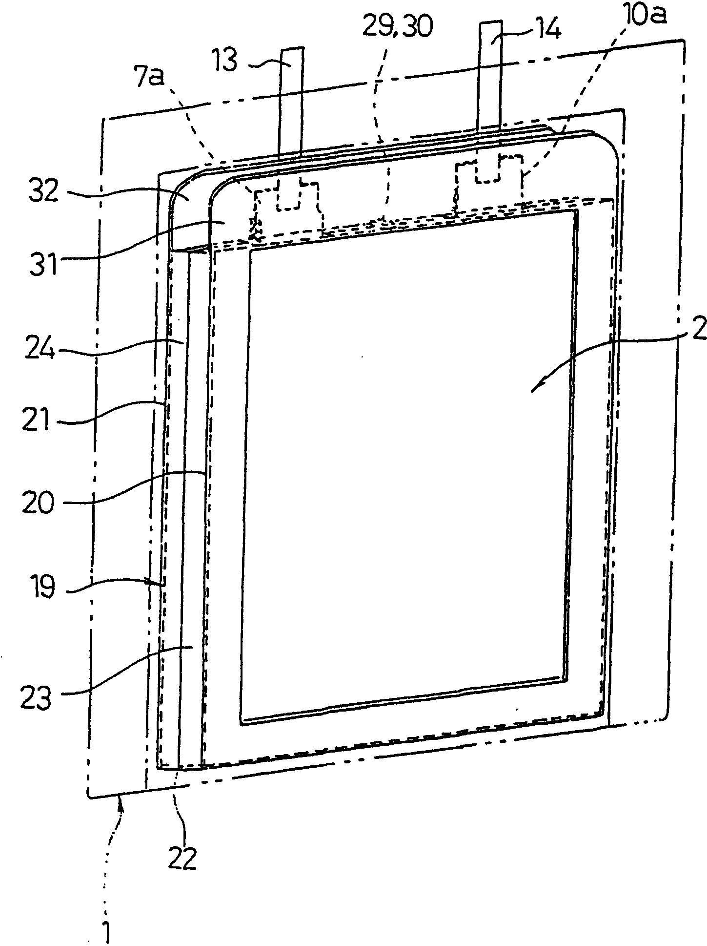
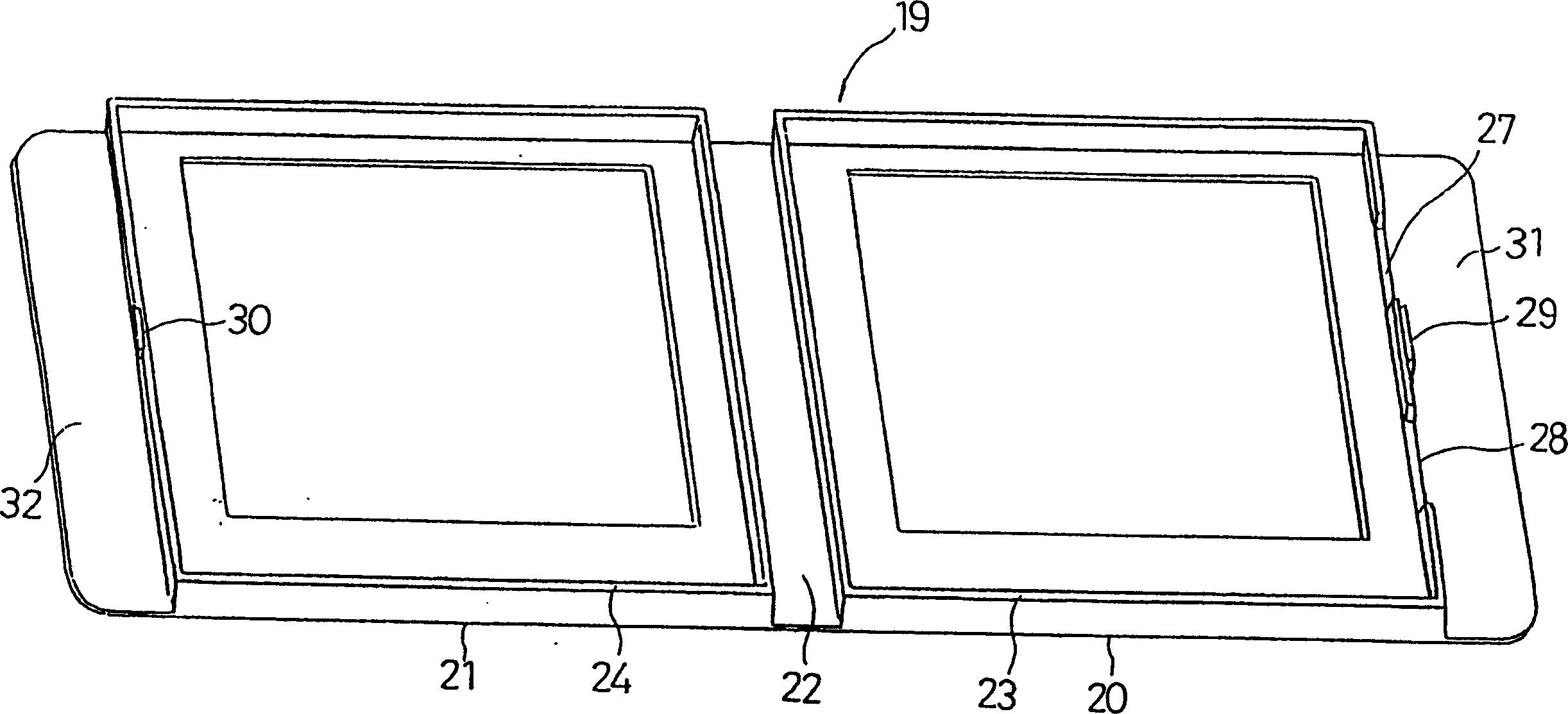
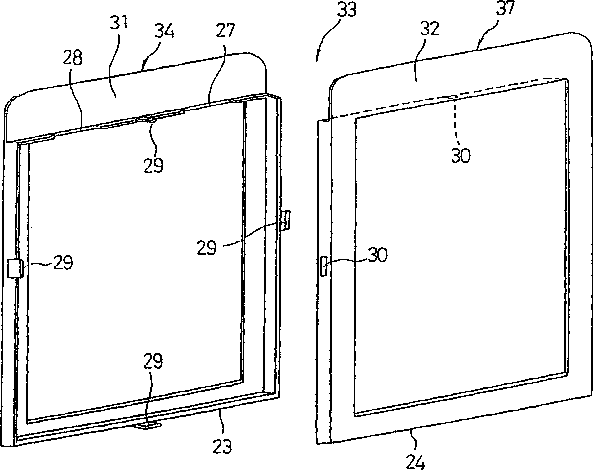
[0076] Hereinafter, preferred embodiments of the present invention will be described with reference to the drawings. The unit electrode group 3 used in the various embodiments described below, the laminated electrode group 2 and the packaging case 1, 18 after it is stacked, and Figure 35 to Figure 40 It is the same as the existing one that has been explained. but Figure 37 The unit electrode group 3 used in the laminated sheet package type battery according to the embodiment of the present invention is shown. First, before describing each embodiment, for the unit electrode group 3 of the sheet-shaped or film-shaped polymer electrolyte constituting the flat laminated electrode group 2, refer to Figure 36 and Figure 37 Provide specific supplementary instructions.

[0077] The unit plate group 3 is formed by stacking a film-shaped or sheet-shaped positive electrode plate 9, a diaphragm 12, and a film-shaped or sheet-shaped negative electrode plate 4. On both sides of the...


PUM


Abstract

Battery with a flexible laminate casing includes a means for fixing the electrode assembly (2) within the casing (1, 18). The fixing means may be a frame (19, 33, 38, 50, 54) attached to the periphery of the electrode assembly, or an insulating spacer (59, 69, 70, 77, 78) encased within the casing together with the electrode assembly such as to fill a space between one end of the electrode assembly and the casing. Alternatively, the fixing means may be constructed of a material with which the casing and the electrode assembly are joined together by applying heat and pressure, or may be an abutting surface (87h) provided to the casing (87) itself such as to make contact with one end face of the electrode assembly within the casing.

Description

[0001] This case is a divisional application of an invention patent application entitled "Laminated Sheet Packaged Battery" with an international filing date of March 27, 2000 and application number 00801285.7 (international application number is PCT / JP00 / 01873). technical field [0002] The present invention relates to a thin laminated sheet packaged battery in which an electric energy generating element is accommodated inside a package case formed by welding the peripheries of two laminated sheets stacked together. Background technique [0003] Laminated sheet-packaged batteries such as lithium polymer secondary batteries have a structure in which a non-aqueous electrolyte power generation element is accommodated in a package case formed of laminated sheets, and are thin and light, so they are used as thin portable batteries. The driving power supply of electric appliances is extremely effective, and it has been widely used in recent years especially as the driving power su...

Claims


Application Information

Patent Timeline
IPC IPC(8): H01G11/00H01G11/08H01G11/10H01G11/12H01G11/22H01G11/74H01G11/76H01G11/78H01G11/80H01G11/82H01G11/84H01M6/10H01M10/02H01M10/04H01M10/05H01M10/058H01M10/0585H01M10/0587H01M50/119H01M50/121H01M50/122H01M50/126H01M50/176H01M50/55H01M50/557H01M50/566
CPCY02E60/12H01M6/10H01M2/0212H01M2/0277H01M10/0436H01M2/021H01M2/06H01M10/0486H01M2/0275Y02E60/10H01M50/557Y02P70/50H01M50/126H01M50/121H01M50/55H01M50/176H01M50/566H01M50/119H01M50/122
Inventor 金田正明吉尾英明松政义高一之濑浩明铃木仁津田信吾
Owner PANASONIC CORP
Why Eureka
Try Eureka