Eureka AIR delivers breakthrough ideas for toughest innovation challenges, trusted by R&D personnel around the world.

Seal device for application in a fan arrangement

A technology of sealing device and installation location, applied in the components of pumping device for elastic fluid, non-variable displacement pump, machine/engine, etc., can solve the problem of wasting working time, achieve fan power data, reduce Noise and loss reduction effect

Inactive Publication Date: 2010-10-06
BSH BOSCH & SIEMENS HAUSGERAETE GMBH
View PDF5 Cites 0 Cited by
  • Summary
  • Abstract
  • Description
  • Claims
  • Application Information

AI Technical Summary

Problems solved by technology

Therefore, many parts are required, and these parts must be installed in a process that wastes working time

Method used


Image

  • Seal device for application in a fan arrangement
  • Seal device for application in a fan arrangement
  • Seal device for application in a fan arrangement

Examples


Embodiment Construction

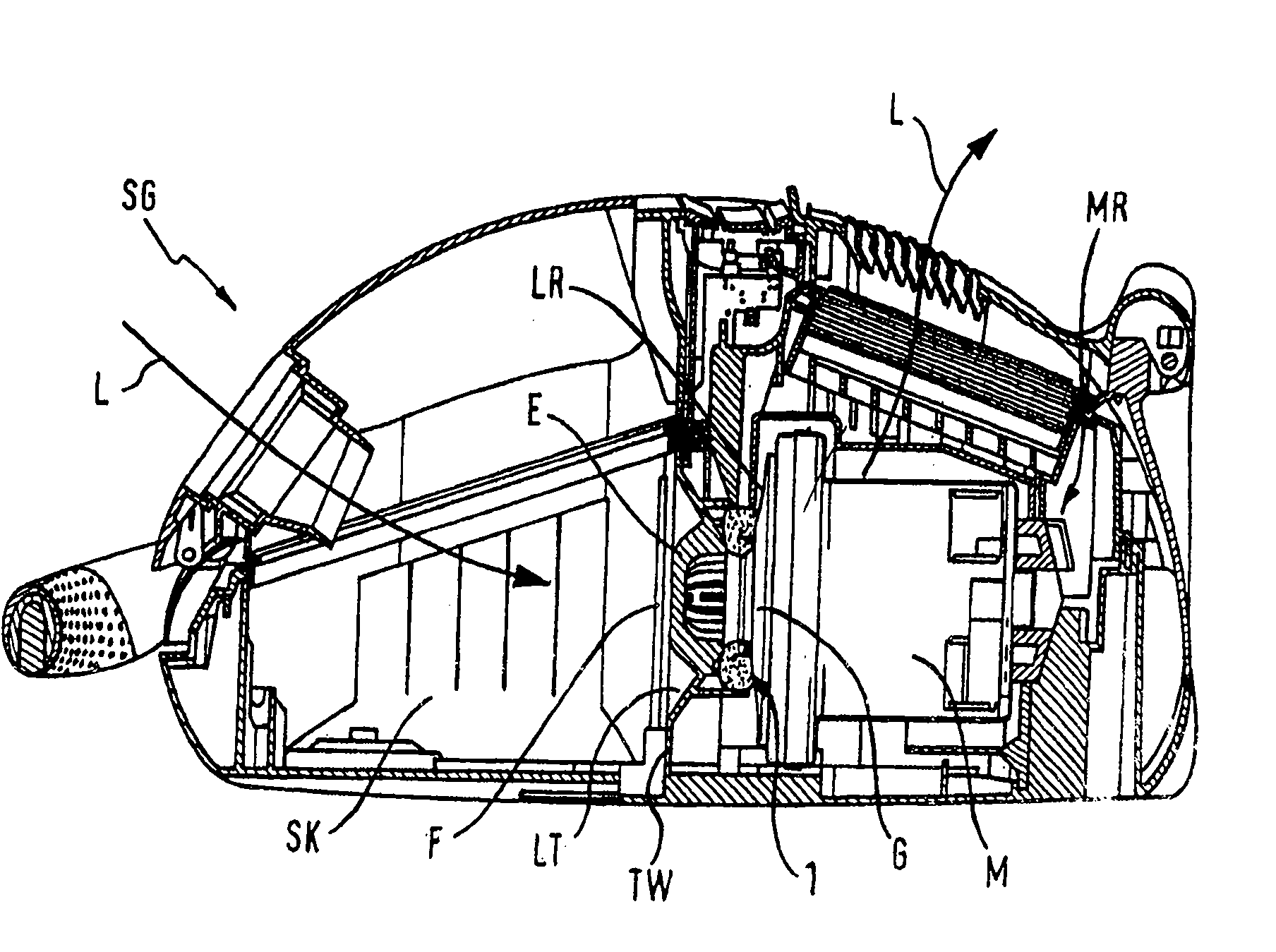
[0022] figure 1 The schematic diagram of is a sectional view taken along the longitudinal axis of the vacuum cleaner housing SG in the case of using the sealing device of the present invention. The vacuum cleaner housing SG subdivides the intake air flow L below into a dust chamber SK which is separated from the motor chamber MR by a partition wall TW with one or more filters F. In the partition TW, an air-guiding funnel LT is provided for space-saving, flow-optimized adjustment of the air flow L to be guided into the housing G.

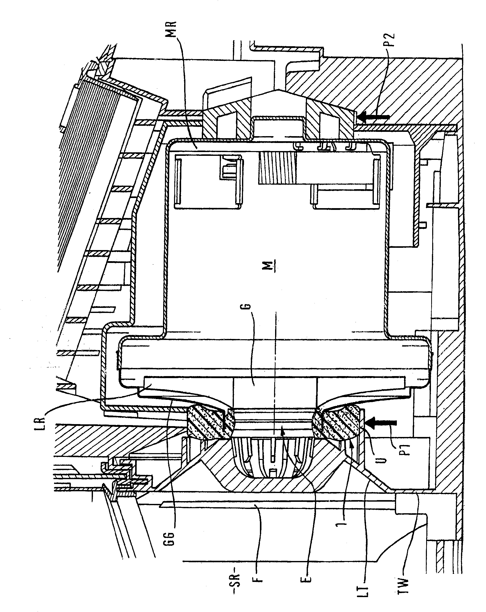
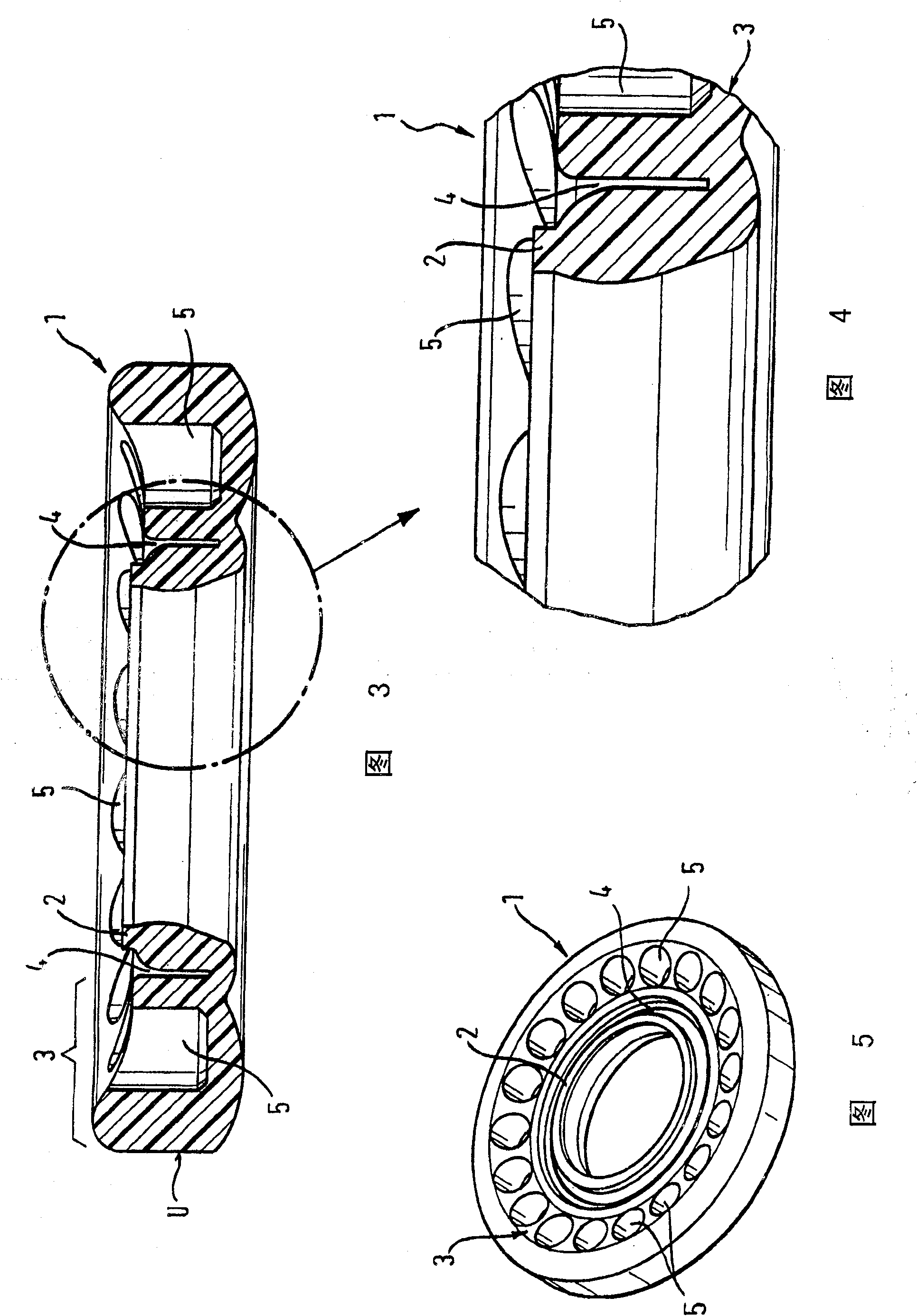
[0023] exist figure 2 In the enlarged cross-sectional view of , the area surrounding the motor M in the motor chamber MR is shown. The two bearing points of the motor M in the motor chamber MR are marked by the arrows P1 and P2, more specifically the bearing points of the motor M on the air guide funnel LT of the partition TW and on an opposite rear wall of the motor chamber MR . Now, in a sectional view, the shape of the device according to the...


PUM


Abstract

The present invention relates to a device for application in a fan arrangement, designed, in particular, to be directly driven by an electric motor. In said fan arrangement, a centrifugal fan wheel is mounted to rotate in unison with a drive shaft. Said centrifugal fan wheel, for inter alia producing a directed airflow, is surrounded by a fan housing. A seal is arranged in an admission orifice, for largely filling in an air gap between said centrifugal fan wheel and the inner surface of said fan housing. The aim of the invention is to develop a device of the aforementioned type, by improving the housing and sealing thereof for an application in a vacuum cleaner. Said aim is achieved, whereby said device (1) is embodied as a sealing ring (2) and said sealing ring (2) is linked to a buffer part (3) out of the fan housing (GG), which tightly surrounds the admission orifice (E).

Description

technical field [0001] The invention relates to a device installed in a fan structure, in particular, the invention relates to a device installed in a fan structure of a household appliance and a fan structure. [0002] In addition, ground maintenance devices and fume extraction hoods also belong to the scope of household appliances. In the domestic appliances mentioned above, fan structures are used which enable the respective delivery capacity to be adjusted within a wide range. Background technique [0003] Fan designs are known from DE-2109409A and DE19717154, which have an electric motor and a centrifugal fan wheel which is connected in a rotationally fixed manner to the output shaft of the motor. In such fan configurations, the centrifugal fan wheel and other components are surrounded by the fan housing to create an aligned air flow that is widened in a frusto-conical manner by the inlet opening for drive by the motor. In the air inlet, the gasket is arranged to larg...

Claims


Application Information

Patent Timeline
IPC IPC(8): F04D29/16
CPCF04D29/162
Inventor T·赛斯D·格里
Owner BSH BOSCH & SIEMENS HAUSGERAETE GMBH
Why Eureka
Eureka Blog
Learn More