Flow field adaptation type demister

A mist eliminator and adaptive technology, applied in chemical instruments and methods, dispersed particle separation, separation methods, etc., can solve the problem of small pressure loss, achieve low energy consumption, reduce manufacturing, and good defogging effect

Inactive Publication Date: 2005-01-12
孙克勤 +3
View PDF0 Cites 66 Cited by
  • Summary
  • Abstract
  • Description
  • Claims
  • Application Information

AI Technical Summary

Problems solved by technology

[0003] Technical problem: In order to overcome the problems existing in the existing demisters, the present invention provides a design of a flow field adaptive demister, which can ensure demisting when th

Method used


Image

  • Flow field adaptation type demister
  • Flow field adaptation type demister
  • Flow field adaptation type demister

Examples


Embodiment Construction

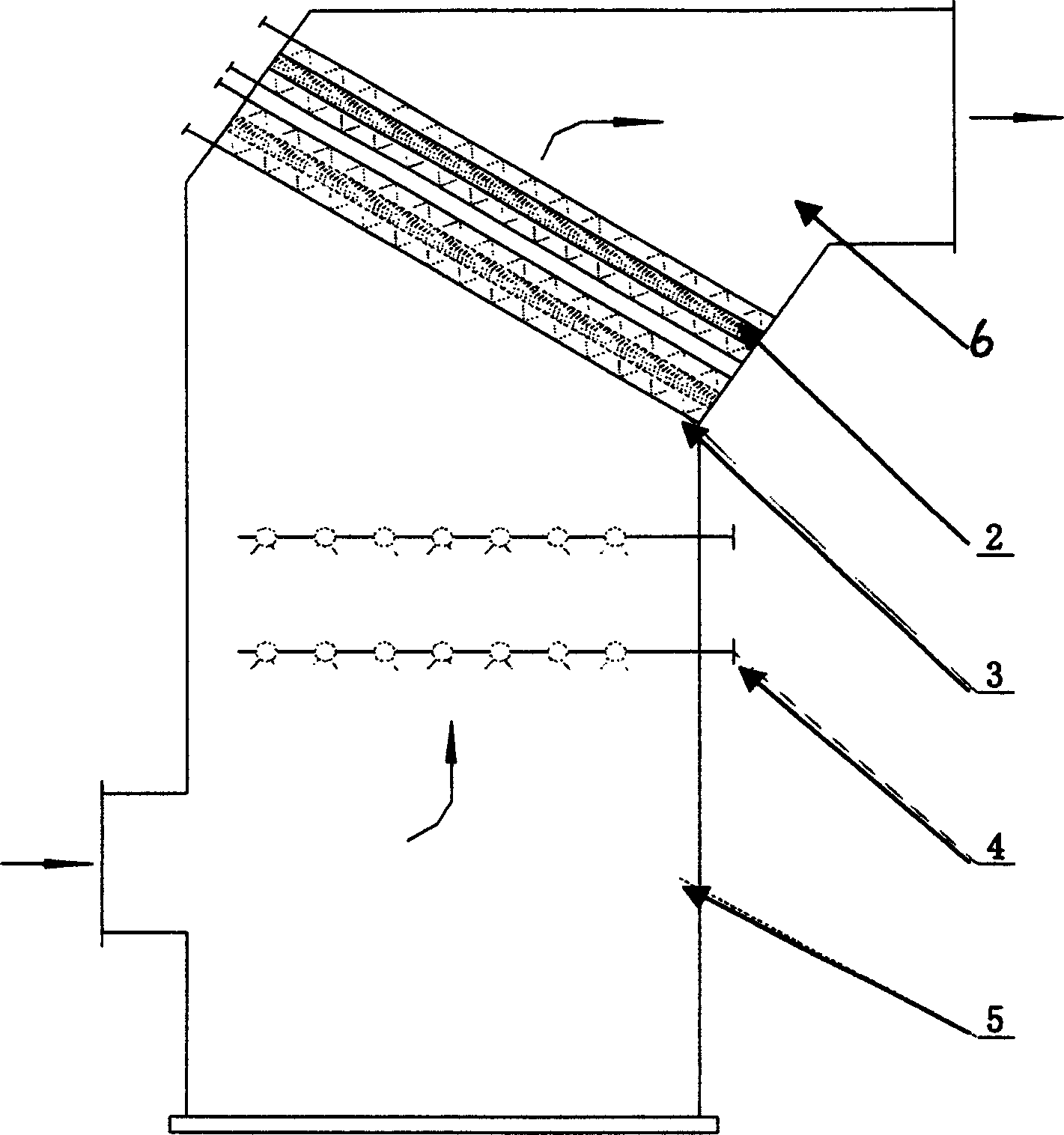
[0013] The flow field adaptable demister of the present invention considers the fluid characteristics of the demister element 2 and the fluid characteristics of the absorption tower slurry spray device 4, the flushing device 3, and the outlet flue 6 before and after it. The fluid characteristics of the mist element are used to form a flow field structure that is most conducive to the function of the demister, and there is no need to change the fluid characteristics of the front and rear devices in order to meet the requirements of the demister. The air inlet of the flow field adaptable demister is located downstream of the slurry spray device 4 of the absorption tower, and the air outlet communicates with the outlet flue 6 of the absorption tower; The upstream and downstream of the demisting element 2 are respectively equipped with flushing devices 3 .

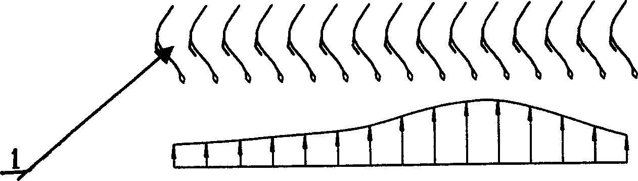
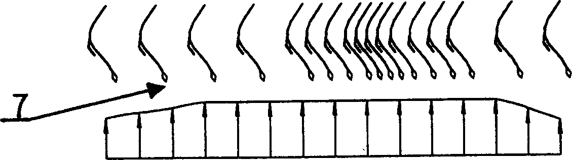
[0014] The baffles 1 in the defogging element 2 are distributed unevenly and in different forms along the flow section, and ...


PUM


Abstract

A flow field adaptive defroster for removing the atomized water from fume is composed of two or more defroster units. Each defroster unit consists of a central defroster element comprising the baffle plates and fume flow field regulating block, and two flushers arranged at both sides of said central defroster element.

Description

technical field [0001] The invention relates to a mist eliminator used in wet flue gas desulfurization system (WFGD) or similar fields to remove water mist in flue gas, especially a mist eliminator which has stronger flow field adaptability than general mist eliminators. fogger. Background technique [0002] Currently known demisters in this field are mainly baffle plate demisters, and the baffles in the demister are evenly arranged along the flow field section. In order to ensure a good demisting effect, theoretically, the upstream and downstream gas flow fields are required to be relatively uniform; in order to avoid secondary entrainment of liquid droplets, there are strict restrictions on the maximum flow rate of flue gas. This brings two problems: one is that it brings difficulties to the design of the flow path upstream and downstream of the mist eliminator, and often increases the manufacturing cost; the other is that the selected mist elim...

Claims


Application Information

Patent Timeline
IPC IPC(8): B01D53/78
Inventor 孙克勤
Owner 孙克勤
Why Eureka
Try Eureka