Supercharge Your Innovation With Domain-Expert AI Agents!

Handle device of foldable inflator

A pump and handle technology, which is applied to liquid variable volume machinery, machines/engines, mechanical equipment, etc., can solve problems such as not easy to operate, and achieve the effect of easy portability and storage, and small overall volume.

Inactive Publication Date: 2005-01-19
黄英哲 +1
View PDF0 Cites 0 Cited by
  • Summary
  • Abstract
  • Description
  • Claims
  • Application Information

AI Technical Summary

Problems solved by technology

[0005] Another object of the present invention is to solve the disadvantage that the foldable handle of the conventional pump is not easy to operate when it is unfolded into an L-shape with the shaft

Method used


Image

  • Handle device of foldable inflator
  • Handle device of foldable inflator
  • Handle device of foldable inflator

Examples


Embodiment Construction

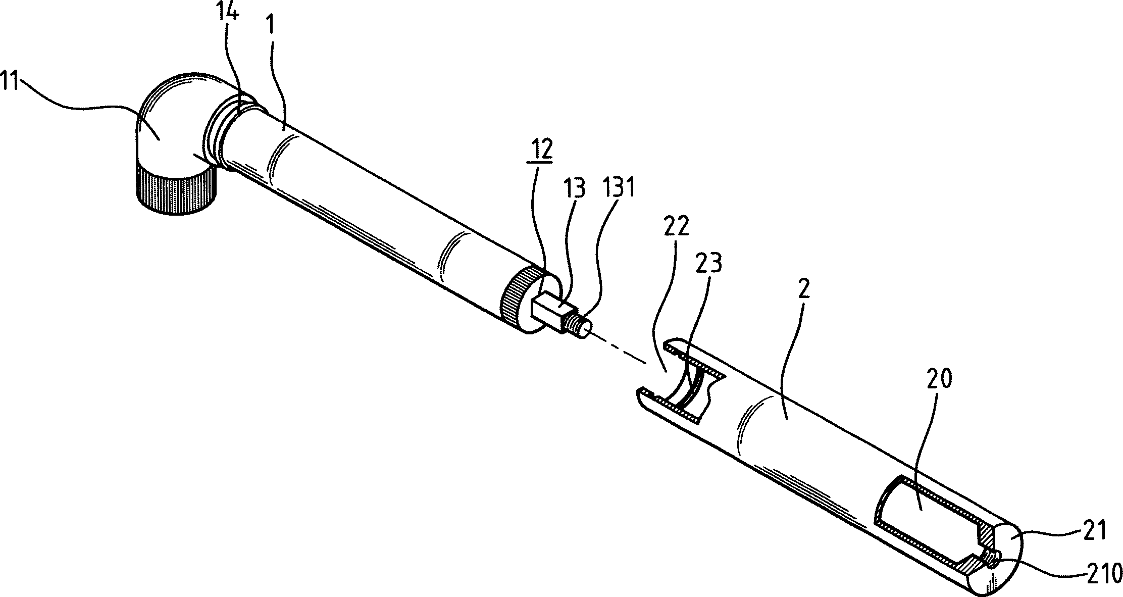
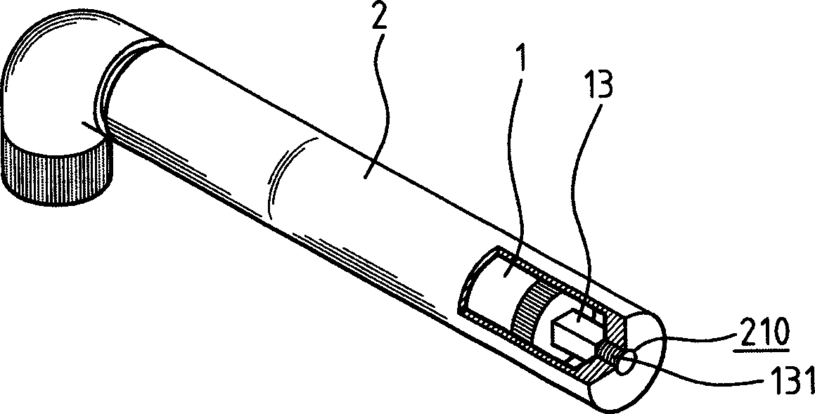
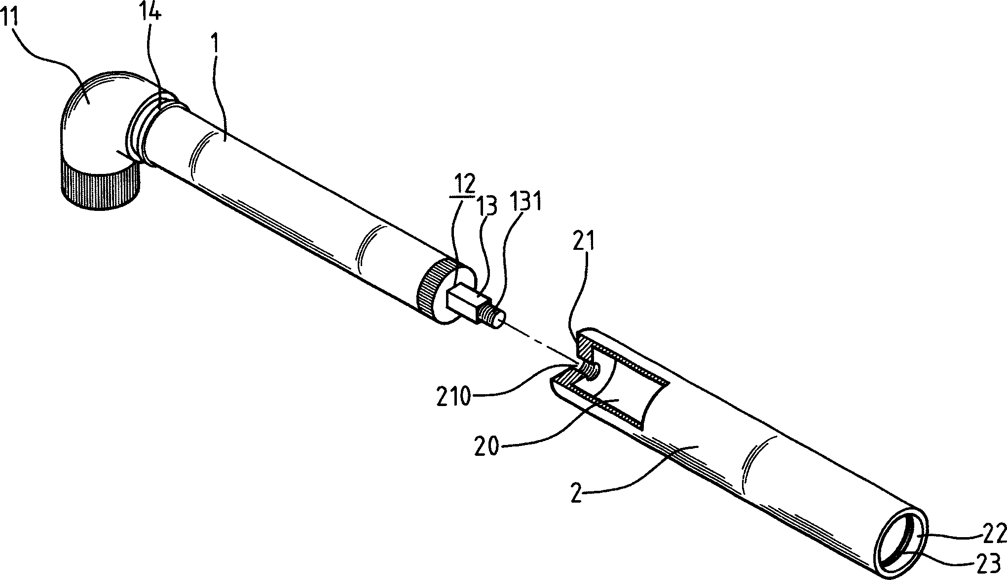
[0019] exist figure 1 Among them, the handle device of the collapsible pump of the present invention includes an air cylinder 1 and a handle 2 that is a hollow tube; the inside of the air cylinder 1 is provided with a piston (not shown in the figure), and the piston is combined with a shaft 13, and make one end of the shaft 13 pass through the perforation 12 provided at one end of the pump 1 to pass through the outside of the pump, a screw 131 is provided at the end of the shaft passing through the outside of the pump, and a nozzle 11 is set at the other end of the pump 1; in order to avoid shaft The rod 13 rotates relatively to the gas cylinder 1, and the cross-sectional shape of the shaft rod 13 and the corresponding end face shape of the perforation 12 adopt a non-circular design; figure 1 Among them, the section of the shaft 13 is rectangular, and the perforation 12 is also rectangular. Therefore, the shaft 13 can only move axially, but cannot rotate; when the shaft 13 mov...


PUM


Abstract

A folding handgrip device for inflator, comprising a inflator with a shaft lever and a hollow handgrip. One end of the shaft lever is linked to the piston in the inflator, the other end is extended to out of the inflator with screw rod arranged on it; on one of the two opposite ends, a surface is arranged, and on the other end, an opening is arranged, on the surface, a screw hole matching the screw rod is arranged; the inflator can be pull into the handgrip through the opening, and the screw rod and the screw hole can be screwed for putting the inflator into the handgrip for reducing volume; when the inflator is used, it can move in the hand grip, also can be taken out, and the screw rod can be locked into screw hole on the surface end, for extending the shaft lever. By moving the shaft lever along axial direction, air can be pumped out from the other end of the inflator.

Description

technical field [0001] The invention relates to an inflation device, in particular to a handle device of an air pump. Background technique [0002] At present, the inflator device with a foldable handle commonly seen on the market is mainly to allow the inflator to be folded with a handle when not in use to reduce the volume, which is convenient for storage or carrying; while in use, Then the handle can be turned out to facilitate hand-held operation. [0003] The known collapsible handle structure of the inflator shown in Fig. 5 is to pivotally connect a handle D with the shaft tip C at the end of the shaft B provided on the inflator A, and the side wall of the handle D is provided with a width A groove D1 larger than the diameter of the shaft B; when not in use, the handle D and the shaft B can be rotated relatively, so that the shaft B can be accommodated inside the handle D through the groove D1, so that the handle D It is located on the same line as the air cylinder A...

Claims


Application Information

Patent Timeline
IPC IPC(8): F04B33/00
Inventor 黄英哲黄俊铭
Owner 黄英哲
Features
  • R&D
  • Intellectual Property
  • Life Sciences
  • Materials
  • Tech Scout
  • Unparalleled Data Quality
  • Higher Quality Content
  • 60% Fewer Hallucinations
Learn More