Door seal cover of microwave oven
A furnace door sealing and microwave oven technology, applied in the field of microwave ovens, can solve the problems of sealing cover deformation, poor heat resistance, moisture infiltration into the furnace door, etc., and achieve the effect of improving reliability
- Summary
- Abstract
- Description
- Claims
- Application Information
AI Technical Summary
Problems solved by technology
Method used
Image

Examples
Embodiment Construction
[0026] Below, the microwave oven door sealing cover provided by the present invention will be described in detail with reference to the accompanying drawings. It should be noted here that, in order to avoid duplication of description, the following parts that are the same as those in the conventional technology refer to the same symbols.
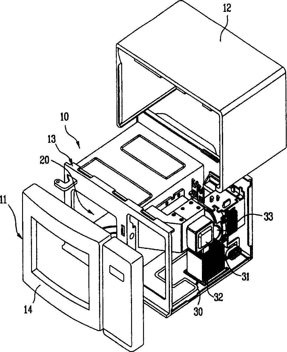
[0027] The present invention is invented on the basis of common microwave ovens, and is applied to common microwave ovens, because the structure of common microwave ovens has been described above. Therefore, a description of the microwave oven is omitted here.
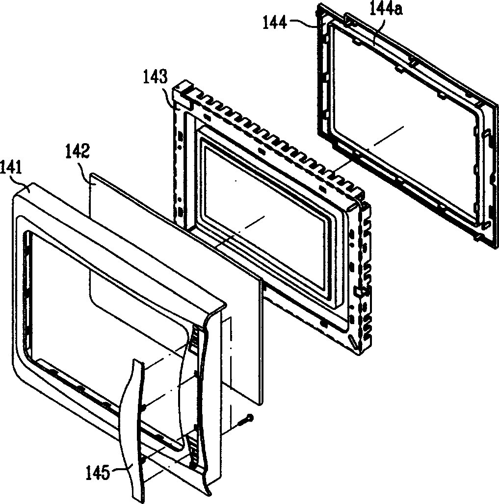
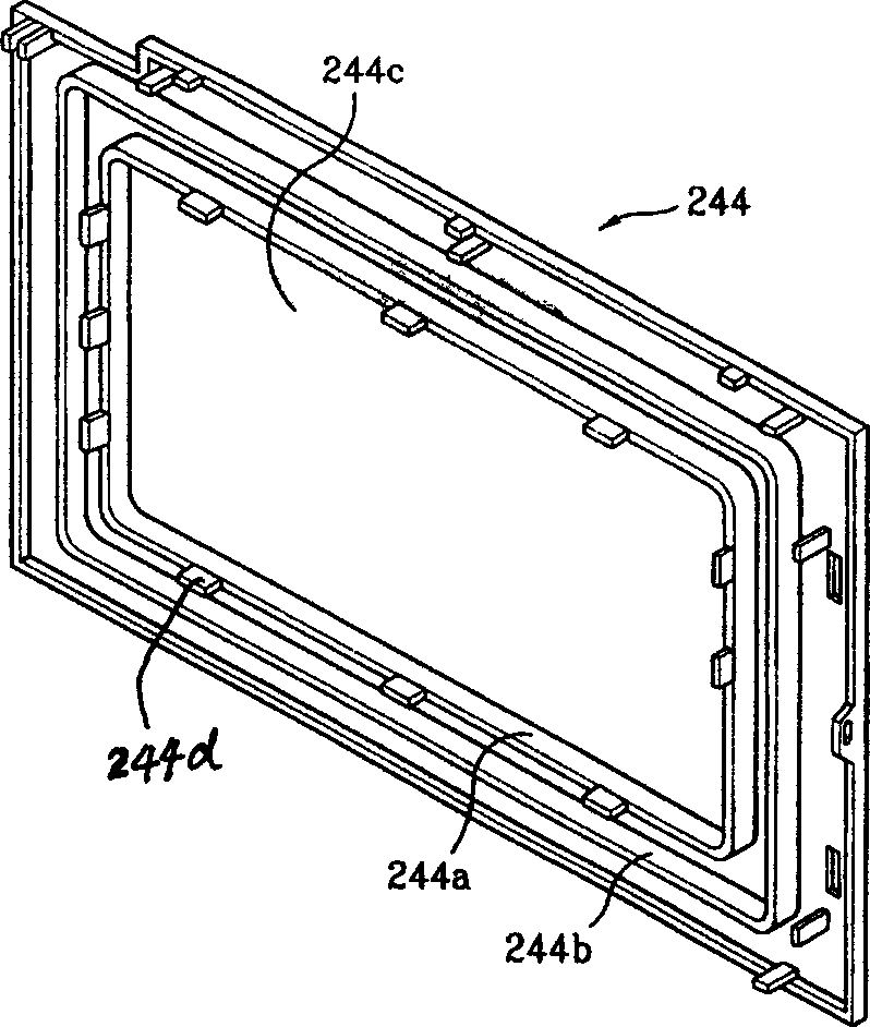
[0028] image 3 It is a schematic diagram of an embodiment of the microwave oven door sealing cover 244 provided by the present invention. Figure 4 It is an exploded schematic view of the furnace door assembly after adopting the sealing cover 244 .
[0029] The sealing cover 244 provided by the present invention has a rectangular appearance, and a quadrangular opening is formed i...
PUM
 Abstract
Description
Claims
Application Information
PatSnap Eureka turns technology decisions into work you can execute. Powered by our Innovation Knowledge Graph, it runs expert workflows across engineering, life sciences, materials and intellectual property. Get your review-ready output in minutes.


