Heat exchanger circuit for air conditioner

A technology for air conditioners and heat exchangers, which is applied to the heat exchange circuit of air conditioners and the heat exchange circuit of air conditioners, can solve the problems of small contact area, weak heat exchange effect, and aggravate the problem of liquid refrigerant flowing into it, so as to achieve energy saving, The effect of preventing compressor breakage and preventing pressure loss

Inactive Publication Date: 2005-01-19
LG ELECTRONICS (TIANJIN) APPLIANCES CO LTD
View PDF0 Cites 10 Cited by
  • Summary
  • Abstract
  • Description
  • Claims
  • Application Information

AI Technical Summary

Problems solved by technology

However, when a capillary tube is used as an expansion device, the adjustment range under load changes is limited, so the problem caused by the inflow of liquid refrigerant may be exacerbated.
[0012] In addition, in the heat exchange circuit of the conventional technology, in order to exchange heat between the low temperature part and the high temperature part of the compressor 1, although attempts have been made to make the pipes of the low temperature part and the high temperature part contact each other, due to the small contact area and the line contact shape, so there is a problem that the heat exchange effect is very weak

Method used


Image

  • Heat exchanger circuit for air conditioner
  • Heat exchanger circuit for air conditioner
  • Heat exchanger circuit for air conditioner

Examples


Embodiment Construction

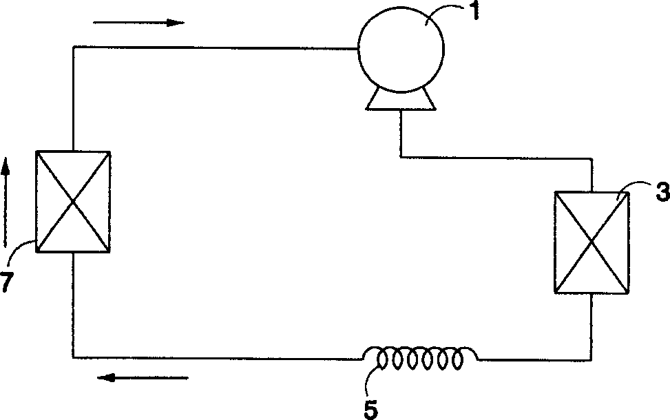
[0031] Below in conjunction with accompanying drawing and specific embodiment the present invention is described in further detail: Figure 4 It is a structural schematic diagram of the heat exchanger of the air conditioner of the present invention. As shown in the figure, the heat exchange circuit includes a compressor 11 , a condenser 13 and an expansion device 15 . Among them, the compressor 11 compresses the refrigerant into a state of high temperature and high pressure. The condenser 13 is a first heat exchanger, and condenses the refrigerant compressed by the compressor. The expansion device 15 depressurizes and expands the refrigerant discharged from the condenser 13 . In addition, the heat exchange circuit further includes an evaporator 17 and a heat pipe 19 . The evaporator 17 is a second heat exchanger that evaporates the refrigerant decompressed and expanded from the expansion device 15, and the heat pipe 19 further evaporates the refrigerant that has passed thro...


PUM


Abstract

The invention discloses a heat exchange loop for an air conditioner. It comprises a first heat exchanger, a expansion gear, a second heat exchanger, a compressor, and a heat pipe. Pressure loss and compressor breakage caused by liquid refrigerant inflow can be prevented, and abnormal noise can be prevented, and energy can be saved.

Description

technical field [0001] The present invention relates to an air conditioner, in particular to a heat exchange circuit of the air conditioner. More specifically, it is an air conditioner heat exchange circuit that uses latent heat to exchange heat between the high temperature part and the low temperature part of the compressor. Background technique [0002] The heat exchange circuit is a circuit that transfers heat between a certain space and its surrounding space, and keeps a certain space at a certain temperature. figure 1 for its circuit diagram. As shown in the figure, the heat exchange circuit is generally composed of a compressor 1 , a condenser 3 , a capillary tube 5 , and an evaporator 7 . [0003] The compressor 1 sucks the vaporized refrigerant from the evaporator 7 , keeps the pressure in the evaporator 7 low, and compresses the sucked refrigerant into a high-temperature and high-pressure gas state, and outputs it to the condenser 3 . [0004] The condenser 3 all...

Claims


Application Information

Patent Timeline
Patent Type & Authority Applications(China)
IPC IPC(8): F25B40/06F28D15/02
Inventor 朴炯真
Owner LG ELECTRONICS (TIANJIN) APPLIANCES CO LTD
Why Eureka
Try Eureka